background image

GB-3

1

2

3

4

5

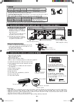
Not running wavy.

Not left in water.

No trap 

allowed.

Not to rise.

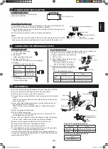
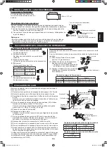
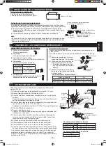
Connecting the drain hose

(1) Connect a drain hose.
(2) Tape over the connecting part.

ø16 mm

4     CONNECTING THE DRAIN HOSE TO THE INDOOR UNIT

No trap allowed.

Notes:

• Be sure to lay the drain hose downward for smooth drainflow. 

• Be careful not to allow the drain hose to rise, form a trap or leave 

its end in water, as shown below.

• Coil thermal insulation around a drain hose extension, if running in 

the room.

Checking drainage

(1) Open the open panel.
(2) Remove the air filters.
(3) Pour some water into the drain pan.
(4) Check the water drains smoothly.

Drain hose 

(Commercially available)

(1) Unhook  and  pull  out 

the drain hose.

(2) Pull out the drain cap.

(3) Reconnect the drain hose and the drain 

cap.


• Fully insert the drain hose until it stops 

and hook on the projection.


• Insert  a  hexagon  wrench  into  the  drain 

cap, and press it fully.

Caution:

  After replacing, make sure that both the 

drain hose and drain cap are firmly inserted.

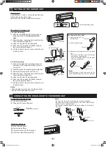
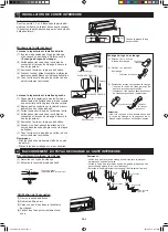
Mounting the indoor unit

For right side piping

(1) Reverse the positions of the drain hose and 

drain cap. Refer to “

Exchange the drain 

hose

”.

(2) Pass the pipes, connecting cable and the drain 

hose through the piping hole. 

(3) Hook the unit onto the mounting plate. 
(4) Push the unit and apply the bottom hooks to 

the mounting plate's support. 

(5) Pull the bottom of the unit to check that the unit 

is fixed in place.

For left side piping

(1) Connect the pipes and wrap tape around the 

insulation of the piping joints tightly not to be-

come thick.

(2) Bind the pipes and connecting cable with tape.
(3) Set the them along the back of the unit. 
(4) Pass the pipes, connecting cable and the drain 

hose through the piping hole. 

(5) Hook the unit onto the mounting plate.
(6) Push the unit and apply the bottom hooks to 

the mounting plate's support. 

(7) Pull the bottom of the unit to check that the unit 

is fixed in place.

Notes:

• Bend the pipes carefully as not to damage them.

• Lay the drain hose below the pipes.

Drain hose

MOUNTING PLATE

Taping

Drain cap

Drain hose

Hexagon wrench

Drain cap

Drain hose

Drain cap

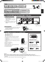
3     SETTING UP THE INDOOR UNIT

Piping route

For directions 1, 2 and 5, cut out the specific zone 

without leaving any sharp edge.

(Keep the cut-out plate for possible future use.)

Plate

Cut the plate along notch.

Plate

Plate

Hook

MOUNTING PLATE

Exchange the drain hose

Drain Hose

Pipes

Tape

AYX36RU_IM_3_lang.indb   3

2014-09-12   07:59:33

Summary of Contents for AE-X36RU

Page 1: ...L EN DEUX PARTIES MANUEL D INSTALLATION ACONDICIONADOR DE AIRE TIPO SPLIT MANUAL DE INSTALACIÓN ENGLISH FRANÇAIS ESPAÑOL INDOOR UNIT OUTDOOR UNIT UNITÉ INTÉRIEURE UNITÉ EXTÉRIEURE UNIDAD INTERIOR UNIDAD EXTERIOR AY X36RU AE X36RU AYX36RU_IM_3_lang indb 1 2014 09 12 07 59 31 ...

Page 2: ...are nut may be broken after a long time and cause refrigerant gas leakage When installing the unit do not to add an air substance other than the specified refrigerant R410A in the refrigerant cycle Otherwise it will cause burst and injury as a result of abnormal high pres sure in the refrigerant cycle Be sure to connect the refrigerant pipe before running the compres sor Otherwise it may burst and...

Page 3: ...ting cable AWG14 Use copper wire Follow local electrical codes Use a double insulated cable with 600 V insulation Cable cover Connecting cable Earth wire Terminal board 2 CONNECTING THE CABLE TO THE INDOOR UNIT Conduit holder Conduit connector Lock nut In case using solid wires Stripping length 0 7 inch 18 mm Be sure to make the wire hook shaped In case using stranded wires Stripping length 0 3 in...

Page 4: ... to Exchange the drain hose 2 Pass the pipes connecting cable and the drain hose through the piping hole 3 Hook the unit onto the mounting plate 4 Push the unit and apply the bottom hooks to the mounting plate s support 5 Pull the bottom of the unit to check that the unit is fixed in place For left side piping 1 Connect the pipes and wrap tape around the insulation of the piping joints tightly not...

Page 5: ...tivity type de signed specially for R410A Gauge manifold Compound gauge Vacuum pump Service port cap 3 way valve Valve shaft cap Valve shaft cap tightening torque Pipe size Torque Liquid side 1 4 14 8 15 5 ft lbs 20 21 N m Gas side 5 8 22 1 23 6 ft lbs 30 32 N m Service port cap tightening torque Torque 5 9 ft lbs 8 N m Installation dimension Referring to the figure firmly fasten the outdoor unit ...

Page 6: ...an cause overheating or fire or malfunction Be sure to use a disconnect switch Follow the local and state elec trical codes Power supply cable Cable holder Connecting cable Earth wire L2 L1 G L1 S L2 0 2 inch 5 mm Conduit holder Conduit connector Lock nut Fit a disconnect switch having a contact separation of at least 0 12 inch 3 mm in all poles to the electricity power line Prepare a dedicated po...

Page 7: ...rant is leaking or there is no refrigerant in the refrigerant cycle Otherwise it will cause burst and injury Gauge manifold Compound gauge 3 way valve 2 way valve Service port FORCED COOLING OPERATION Following procedures should be completed within 5 minutes after turning on the circuit breaker 1 Press the ON OFF button to start operation 2 Press the MODE button to select cooling mode 3 Set the te...

Page 8: ...r une fuite de gaz réfrigérant Durant l installation de l unité ne faites pas faire entrer de gaz autre que le gaz réfrigérant R410A dans le circuit de réfrigération Dans le cas contraire le circuit de réfrigération pourrait être soumis à des pressions anormalement élevées et risquerait d exploser et de causer des blessures Assurez vous de connecter la conduite de réfrigérant avant de faire tourne...

Page 9: ...n fil massif ou tressé Câble de raccordement AWG14 Utilisez un fil en cuivre Respectez les codes électriques locaux Utilisez un câble à double isolation avec une isolation de 600 V Cache câble Câble de connexion Fil de terre Borne de branchement 2 RACCORDEMENT DU CÂBLE A L UNITÉ INTÉRIEURE Porte conduite Connecteur de conduite Contre écrou En cas d utilisation de fils massifs Longueur de dénudage ...

Page 10: ...uyau de vidange à travers le trou de tuyauterie 3 Accrochez l unité sur la plaque de fixation 4 Poussez l unité et glissez les attaches inférieures dans les supports prévus sur la plaque de fixation 5 Tirez l unité vers le bas afin de vérifier qu elle est correctement accrochée Lorsque la tuyauterie est installée à gauche 1 Connectez la tuyauterie et enroulez du ruban adhésif autour de l isolation...

Page 11: ...pour le R410A Manomètre Manomètre à pression positive et négative Pompe à vide Capuchon de l orifice de sortie Soupape à 3 voies Capuchon de tige de soupape Couple de serrage du capuchon de tige de soupape Taille de la conduite Couple Côté liquide 1 4 20 21 N m 14 8 15 5 ft lbs Côté gaz 5 8 30 32 N m 22 1 23 6 ft lbs Couple de serrage du capuchon de l orifice de sortie Couple 8 N m 5 9ftlbs Dimens...

Page 12: ...tion Faites bien attention à ne pas confondre les branchements Un mauvais branchement peut causer des dommages au circuit interne de contrôle Assurez vous de connecter le câble correspondant aux marquages des bornes de raccordement sur l unité extérieure et sur l unité intérieure Assurez vous d enfoncer les extrémités des câbles profondé ment dans la borne de connexion et de serrer les vis Un mauv...

Page 13: ...ns le cycle frigorifique Le non respect de cette consigne peut causer une explosion et des blessures Manomètre Manomètre à pression positive et négative Soupape à 3 voies Soupape à 2 voies Orifice de sortie FONCTION DE REFROIDISSEMENT FORCÉ Les procédures suivantes doivent être effectuées moins de 5 minutes après l enclenchement du disjoncteur 1 Appuyez sur la touche MARCHE ARRÊT ON OFF pour comme...

Page 14: ...frigerante Al instalar la unidad tenga cuidado de no introducir otro gas que no sea el refrigerante especificado R410A en el circuito de refrigeración De lo contrario podrían originarse explosiones o heridas como resultado de una presión alta anormal en el circuito del refrigerante Asegúrese de conectar la tubería del refrigerante antes de poner en marcha el compresor De lo contrario podrían origi...

Page 15: ...a abajo y hacia afuera L1 S G L2 Utilice cable rígido o flexible Cable de conexión AWG14 Utilice cable de cobre Siga los códigos eléctricos locales Utilice un cable de doble aislamiento con aislamiento para 600 V Cubierta de los cables Cable de conexión Cable de toma de tierra Tablero de bornes 2 CONEXIÓN DEL CABLE A LA UNIDAD INTERIOR Sujetaconductos Conector de conductos Contratuerca En caso de ...

Page 16: ...2 Pase las tuberías el cable de conexión y la manguera de desagüe a través del orificio de salida de tubos 3 Enganche la unidad a la placa de montaje 4 Empuje la unidad y fije los enganches inferio res a la base de la placa de montaje 5 Tire de la parte inferior de la unidad para ase gurarse de que ha quedado firmemente sujeta Para la tubería del lado izquierdo 1 Conecte las tuberías y envuelva co...

Page 17: ... Bomba de vacío Tapón del puerto de servicio Válvula de 3 vías Tapón del árbol de las válvulas Par de apriete del árbol de válvulas Tamaño de la tubería Par Lado del líquido 1 4 20 21 N m 14 8 15 5 ft lbs Lado del gas 5 8 30 32 N m 22 1 23 6 ft lbs Par de apriete del puerto de servicio Par 8 N m 5 9 ft lbs Dimensión de la instalación Sujete firmemente la unidad exterior con pernos como se indica e...

Page 18: ...n Tenga cuidado de no confundir las conexiones de los terminales ya que un cableado incorrecto podría dañar el circuito de control interno Asegúrese de conectar el cable según las marcas del panel de terminales de la unidad exterior y la de la unidad interior Asegúrese de introducir correctamente el cable en el panel de bornes y apretar los tornillos Un mal contacto puede causar un calentamiento e...

Page 19: ... el BOMBEO cuando haya una fuga de refrigerante o no haya refrigerante en el ciclo del refrigerante De lo contrario estallará y podría provocar lesiones Manómetro Indicador del manómetro Válvula de 3 vías Válvula de 2 vías Puerto de servicio MODO DE FRÍO FORZADO Los siguientes procedimientos deben completarse en 5 minutos después de activar el interruptor de corte 1 Pulse la tecla ON OFF para pone...

Page 20: ...AYX36RU_IM_3_lang indb 7 2014 09 12 07 59 44 ...

Reviews: