

ENGLISH
EN-2
1/2"
3/8"
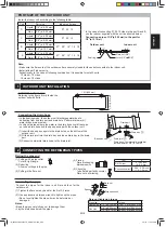
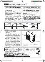
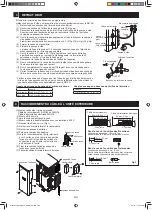
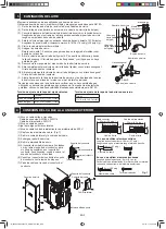
Connecting the drain hose
• In the heating mode, the outdoor unit discharges water due to
defrosting from its drain port and drain hole. Perform drain work if
water drops are a problem.
• In very cold areas where the water in the drain hose could freeze, do
not use a drain hose and the base pan cap with the outdoor unit.
(1) Insert the base pan caps into the drain holes on the bottom of the
outdoor unit.
(2) Fit the drain joint into the drain tray and insert drain tray to the drain
port.
(3) Connect commercial drain hose to the drain joint.
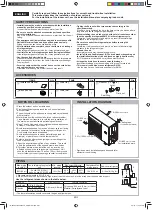
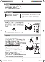
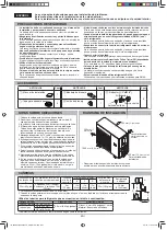
Installation dimension
Referring to the fi gure, fi rmly fasten the
outdoor unit with bolts.
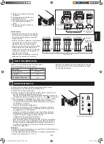
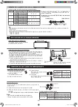
Install the indoor unit according to the following table.
Port
Port size
Indoor unit class
D
Liquid
1/4" (ø 6.35 mm)
07 09 12
Gas
3/8" (ø 9.52 mm)
C
Liquid
1/4" (ø 6.35 mm)
07 09 12
Gas
3/8" (ø 9.52 mm)
B
Liquid
1/4" (ø 6.35 mm)
07* 09* 12* 15 18
Gas
1/2" (ø 12.7 mm)
A
Liquid
1/4" (ø 6.35 mm)
07* 09* 12* 15 18
Gas
1/2"(ø 12.7 mm)
1 OUTDOOR UNIT INSTALLATION
Drain hose (Commercially available)
Inside diameter: 5/8" (ø 16 mm)
Drain port
Drain tray
3
Drain joint
4
Note:
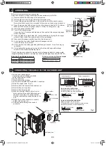
• Make sure the fl are nuts of the outdoor unit are securely closed for those not connected to the indoor unit.
• Install at least 3 indoor units.
Exceptionally, in the case of following combination, it is possible to install 2 units.
15 class + 18 class
18 class + 18 class
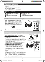
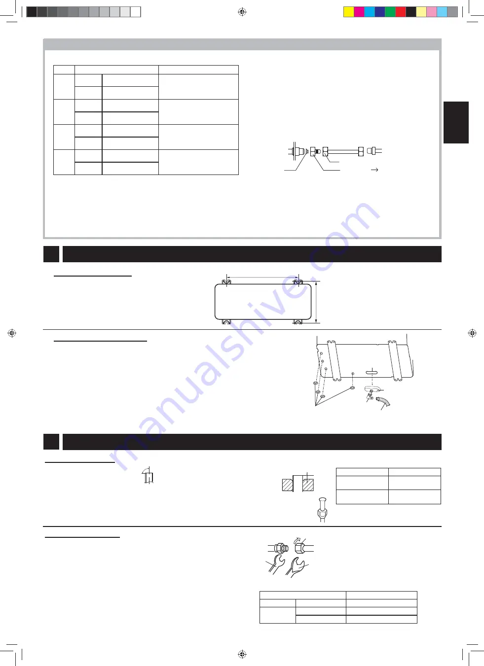
Joint (1/2"
3/8")
Seal ring
Flare nut (3/8")
Outdoor unit
Indoor unit
PORT SIZE OF THE OUTDOOR UNIT
Base pan cap
2
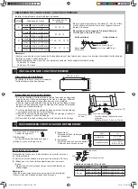
Connecting the pipes
Connect the pipes for the indoor unit first and then for the
outdoor unit.
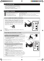
(1) Tighten the fl are nuts by hand for the fi rst 3-4 turns.
(2) Use a spanner and torque wrench to tighten up the pipes.
• Do not over tighten the pipes; it may be deformed or
damaged.
Notes:
• Bend the pipes carefully as not to damage them.
• Lay the drain hose below the pipes.
(4) Flaring
Flare
processing
dimensions(A)
(5) Checking
To
be
fl ared perfectly circular.
Flare nut not missing.
Flare nut
Flaring the pipe end
(1) Cutting with a pipe cutter
Cut at a right angle.
(2) Deburring
Allow no cuttings in the pipe.
(3) Putting in the fl are nut
90°
A
Tool
A
R410A tool
0 - 0.02 inch
(0 - 0.5 mm)
Conventional tool
0.04 - 0.06 inch
(1.0 - 1.5 mm)
Spanner
Torque wrench
Flare nut tightening torque
Pipe size
Torque
Liquid side
1/4" (ø 6.35 mm)
11.8±1.5 ft·lbf (16±2 N·m)
Gas side
3/8" (ø 9.52 mm)
28.0±3.0 ft·lbf (38±4 N·m)
1/2" (ø 12.7 mm)
40.6±3.7 ft·lbf (55±5 N·m)
2 CONNECTING THE REFRIGERANT PIPES
* In the case of connecting 07, 09,12 class to the port A and B,
use the reducer supplied with the unit as directed below.
Connecting a pipe of 3/8"(ø 9.52 mm) to the port for
1/2"(ø 12.7 mm).
1.9 ft (590 mm)
1.2 ft (361 mm)
IM_A3AEX4M3PU(B434)_EN+FR+ES.indb EN-2
IM_A3AEX4M3PU(B434)_EN+FR+ES.indb EN-2
2/7/13 11:05:28 AM
2/7/13 11:05:28 AM


