


OPERATION MANUAL
INDOOR UNIT OUTDOOR UNIT
AH-PN10 AU-PN10
AH-PN10-GY AU-PN10
AH-PN13 AU-PN13
AH-PN13-GY AU-PN13
AH-PN19 AU-PN19
AH-PN24 AU-PN24
AH-L10 AU-L10
AH-L13 AU-L13
CONTENTS
Page
IMPORTANT SAFETY
INSTRUCTIONS
1
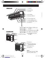
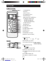
PART NAMES
2
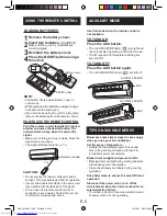
USING THE REMOTE
CONTROL
5
AUXILIARY MODE
5
TIPS ON SAVING
ENERGY
5
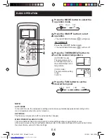
BASIC OPERATION
6
ADJUSTING THE AIR
FLOW DIRECTION
7
POWERFUL JET
OPERATION
7
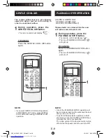
GENTLE COOL AIR
8
PLASMACLUSTER
OPERATION
8
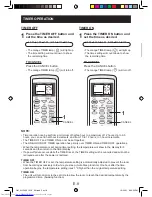
TIMER OPERATION
9
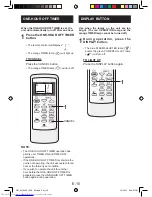
ONE-HOUR OFF TIMER
10
DISPLAY BUTTON
10
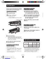
MAINTENANCE
11
OPERATING CONDITION
11
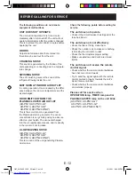
BEFORE CALLING FOR
SERVICE
12
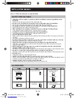
INSTALLATION MANUAL
13
AH-PN10, 10GY AH-L10
AH-PN13, 13GY AH-L13
AH-PN19, AH-PN24
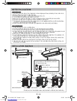
INSTALLATION MANUAL
Thank you for purchasing a SHARP air conditioner.
Please read this manual carefully before operating
the product
OM_AH-PN10 13GY_EN.indd 1
OM_AH-PN10 13GY_EN.indd 1
12/22/11 6:30:07 PM
12/22/11 6:30:07 PM


