
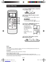

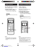
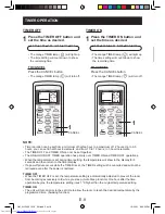
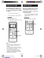


ENG-
E-15
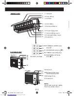
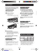
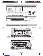
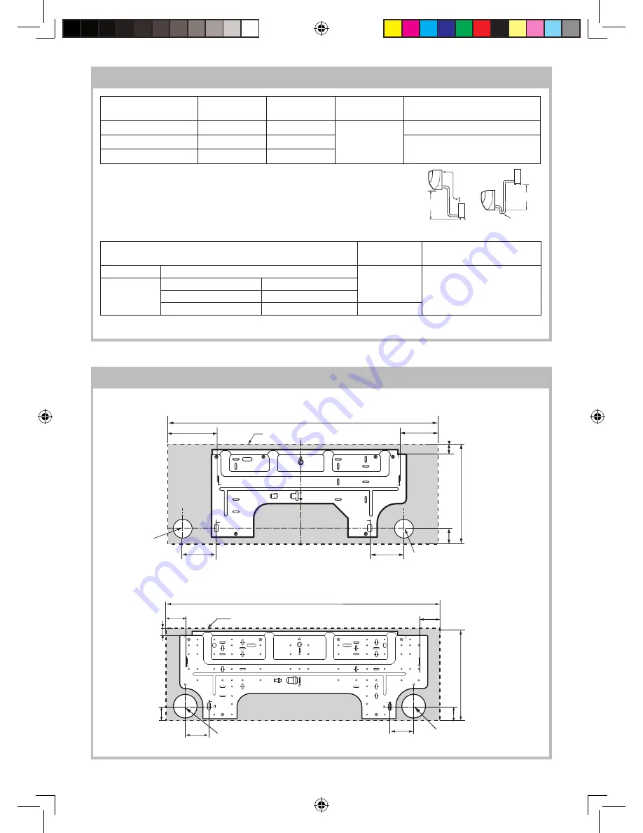
INSTALLATION DIMENSION OF INDOOR UNIT
860
108
A
125
J
175
115
I
F
E
D
J
E
A
F
I
D
292
45
30
Length unit: mm
Center of wall hole
Center of
wall hole
Outline of indoor unit
(Unit size)
965 (Unit size)
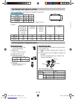
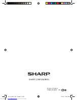
Model
Max. piping
length:A
Max. height
difference:B
Min. piping
length
Additional refrigerant
(piping length exceeds 7.5m)
9K-Btu/h type
10 m
5 m
1 m
15 g/m
12K-Btu/h type
15 m
7 m
10 g/m
18K 24K-Btu/h type
15 m
10 m
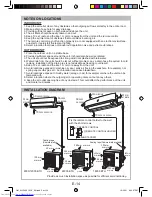
• Standard piping length is 7.5m.
• When the outdoor unit is placed at a higher level than the indoor
unit, provide a trap near the hose’s lead-in port.
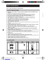
Use the refrigerant pipes shown in the table below.
Pipe size
Pipe
thickness
Thermal insulation
Liquid side
1/4" (ø 6.35 mm)
0.8 mm
Thickness: 6 mm or
thicker
Material: Polyethylene
foam
Gas side
9K-Btu/h type
3/8" (ø 9.52 mm)
12K-Btu/h type
1/2" (ø 12.7 mm)
18K 24K-Btu/h type
5/8" (ø 15.88 mm)
1.0 mm
• The thermal insulation should cover both the gas and liquid pipes.
Trap
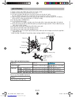
PIPES
A
B
B
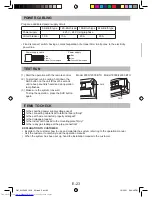
31
3
05
05
80
A
J
I
80
88
88
F
42
E
E
E
C
A
B
J
H
G
F
0
0
I
D
D
Length unit: mm
Center of wall hole
Center of wall hole
Outline of indoor unit
(Unit size)
965 (Unit size)
9000/12000 BTU
18000/24000 BTU
OM_AH-PN10 13GY_EN.indd Sec1:15
OM_AH-PN10 13GY_EN.indd Sec1:15
12/22/11 6:30:28 PM
12/22/11 6:30:28 PM


