background image

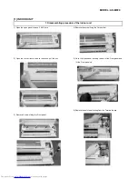
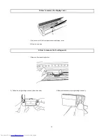
13) Remove 2 screws fixing the Control box and remove it.

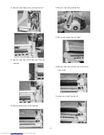
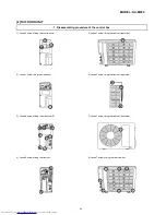
16) Remove 3 screws fixing the Evaporator.

17) Remove the Evaporator from the Cabinet.

14) Remove a screw fixing the drain pan and pull Drain pan

       toward you.

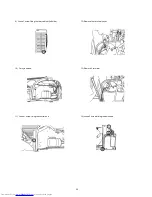
18) Remove 4 screws fixing the Side cover R, and pull the -

       Cross flow fan

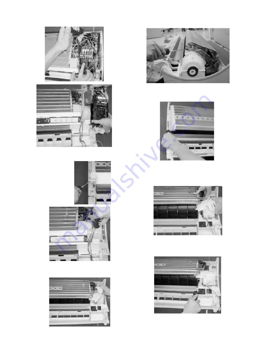
19) Loose a screw  fixing Cross flow fan.

15) Remove the Drain cover from the Evaporator

19

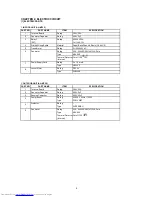
Summary of Contents for AH-MP20

Page 1: ... CONTROL SYSTEM 6 PRINTED WIRING DIAGRAM 7 FUNTIONS 8 TROUBLESHOOTING 12 REFRIGERATION CYCLE AND PERFORMANCE CURVES 15 DISASSEMBLING PROCEDURE 17 REPLACEMENT PARTS LIST 27 SERVICE MANUAL SPLIT SYSTEM ROOM AIR CONDITIONER INDOOR UNIT AH MP20 OUTDOOR UNIT AU MP20 SHARP CORPORATION CONTENTS 1 ...

Page 2: ...r Internal protector Fan motor Thermal protector Internal Fuse Micro computer control Fan Propeller fan Connections Drive Direct drive m3 min 44 m3 min Air flow quantity Refrigerant system Evaporator Louver fin and Grooved tube type Condenser Louver fin and Grooved tube type Control Capillary tube Refrigerant volume R22 1300g Power factor 92 98 Compressor Type Hermetically sealed rotary type Model...

Page 3: ... 2 EXTERNAL DIMENSION 3 1 Indoor unit AH MP20 2 Outdoor unit AU MP20 ...

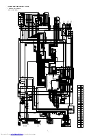
Page 4: ...4 Indoor Unit AH MP20 Outdoor Unit AU MP20 3 WIRING DIAGRAM CC097 UNIT TO UNIT CORD ...

Page 5: ...ating 220 240VAC 50Hz 41W 4 Pole Type MLA999 Thermal Protector Cut off 135 10 C Internal 7 Power Supply Cord Rating 3 x 1 5 mm2 Type H05VV F 8 Louver Motor Rating DC12V Type 24BYJ48 1 OUTDOOR UNIT AU MP20 PART NO PART NAME ITEM SPECIFICATION 1 Terminal Board Rating 300V 25A 2 Fan motor Capacitor Rating 450V 3µF 3 Running Capacitor Rating 400V 45µF 4 Compressor Rating AC220V 50Hz 1730W Type PH31VNE...

Page 6: ...K 10K 10 16V 16V 10 10k F 10K F 4 3 2 1 TH2 PIPE TEMP 15k 25ыC TH1 PIPE TEMP 10k 25ыC FAN MOTOR 2 1 3 5 2 7K F D7 35V 1000 50V 0 1 7812 IC2 25V 47 7805 0 1 IC3 25V 10V 100 C7 D1 4 GND 22 6K F 3 3K 4 5 IC8 1 2 3 8 7 6 0 1 25V 16V 0 01 TR1 C1 C2 C3 C4 C5 C6 C8 C9 C11 C13 C14 C15 C17 C18 C19 C20 C21 C23 C25 R7 R8 R9 R10 R13 R14 R15 R16 R18 R19 R20 R21 R22 R23 R24 R25 R26 R32 R34 10K 16V 16V 16V 0 01 ...

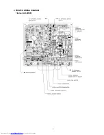
Page 7: ...2 PRINTED WIRING DIAGRAM 1 Indoor AH MP20 7 ...

Page 8: ...D1 to D3 and the compressor and the fan motor are controlled in each zone as shown in Table DL Cooling zone ON DH Dehumidifying zone ON 2 2 DRY On the switch on the compressor always starts to operate for 2 minutes with fan speed DL The microcomputer reads the room temperature 2 minutes after this first compressor operation This room temperature is set as the preset temperature t ti ll Circulating...

Page 9: ...E HOUR timer is set the unit turns off automatically after one hour The one hour timer operation has priority over other time operation such as the TIMER ON and TIMER OFF If the ONE HOUR TIMER button is pressed again during operation the unit will operate additionally for another one hour AUTOMATIC AIR CONDITIONING When automatic air conditioning is selected the operation mode and preset temperatu...

Page 10: ...ushing the AUX button in the unit or the OI button in the remote controller Normal outputs are shown in Table 2 1 PLASMA CLUSTER Plasma cluster ion mode SSR2 ON Relay Cluster unit inside OFF Minus ion mode SSR2 ON Relay Cluster unit inside ON 1 Cluster generator checking STEP 1 Time LED ON OFF Yellow Judgement Normal Failure Generator OK Check circuit ...

Page 11: ...d the unit is free from DIAGNOSIS PROCEDURE When indoor fan motor is out of order or compressor lock occurs indoor fan motor outdoor fan motor and louver are all stopped and the operation LED red turns on or off synchronously with the timimg of the timer LED When the thermistor for room temperature or pipe temperature is open or short state the operation LED turns on or off synchrnoously with the ...

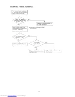
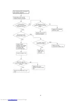
Page 12: ...CHAPTER 4 TROUBLESHOOTING 12 ...
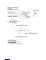
Page 13: ...13 ...

Page 14: ......

Page 15: ...CHAPTER 5 REFRIGERANTION CYCLE AND PERFORMANCE CURVES O D I D L 3 5 2 0 80 15 Capillary tube 1 REFRIGERANT CYCLE ...

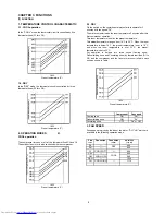
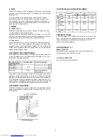
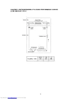
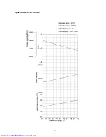
Page 16: ...1 14 16 2 PERFORMANCE CURVES ...

Page 17: ...ove 2 Air Filters 4 Remove the screw fixing the Cord holder 2 Open the Louver frame unlooks the hooks pull the unit 5 Close the Open panel pushing the nail of the Front panel and lift the Front panel up 6 Remove the unit to unit wiring from the Terminal board 3 Remove 6 screws fixing the Front panel ...

Page 18: ...ing the Control box cover 10 Remove the Thermistor of the Evaporator 11 Remove Connector 8 Cut the fixing band and remove the Cover B 12 Cut the fixing band and remove the Holder 9 Remove a screw fixing the ground wire 18 ...

Page 19: ...the Evaporator 17 Remove the Evaporator from the Cabinet 14 Remove a screw fixing the drain pan and pull Drain pan toward you 18 Remove 4 screws fixing the Side cover R and pull the Cross flow fan 19 Loose a screw fixing Cross flow fan 15 Remove the Drain cover from the Evaporator 19 ...

Page 20: ... Receiving filter 4 Remove a screw fixing the Cord holder and 2 screw fixing the Terminal board 2 Remove the 2 Switch and Photo detector unit 5 Remove 2 screws fixing the Transformer and pull the Control board unit 3 Remove a screw fixing the Cord holder 20 ...

Page 21: ...3 The Drain pan and related 1 Remove the screw fixing the Drain pan on both side 2 Turn left the Drain hose 21 ...

Page 22: ...he screw fixing the frame guide on both side 3 Remove the connector of louver motor and take off the and take off the louver unit wire and holder 4 Put the one of the vertical louver 2 Remove 2 screws fixing cover l and cover r and take off them 22 ...

Page 23: ...enter of the front panel under the display cover 2 Side it to one side 6 How to remove the hi voltage unit 1 Remove 2 screws fixing holder 2 Take off the high voltage unit ass y from the holder 3 Remove the connector of high voltage unit ass y 23 ...

Page 24: ...trol cover 5 Loose 1 screw fixing the cabinet rear side 2 Loose 1 screw fixing the side cover 6 Loose 3 screw fixing the cabinet right side 3 Loose 8 screws fixing the side cover R 7 Loose 1 screw fixing the cabinet front side 4 Loose 2 screws fixing the cabinet 8 Loose 7 screws fixing the rear cabinet 24 ...

Page 25: ...9 Loose 1 screw fixing the rear cabinet left side 12 Remove the terminal cover 10 Cut nylon band 13 Remove 3 terminal 11 Loose 1 screw fixing the control box 14 Loose 3 screws fixing the bulkhead 25 ...

Page 26: ...2 Disassembling procedure of the fan 1 Loose the fan nut and fan can take out 2 Loose 2 screw fixing the fan motor angle 3 Cut the nylon band and loose 4 screws fixing the fan motor 26 ...

Reviews: