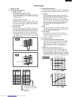
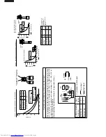
background image

PERFORMANCE CURVES

NOTE: 1) Indoor fan speed: Hi

2) Vertical adjustment louver "45˚", Horizontal adjustment louver "front"
3) Indoor air temp. : Cooling 27˚C
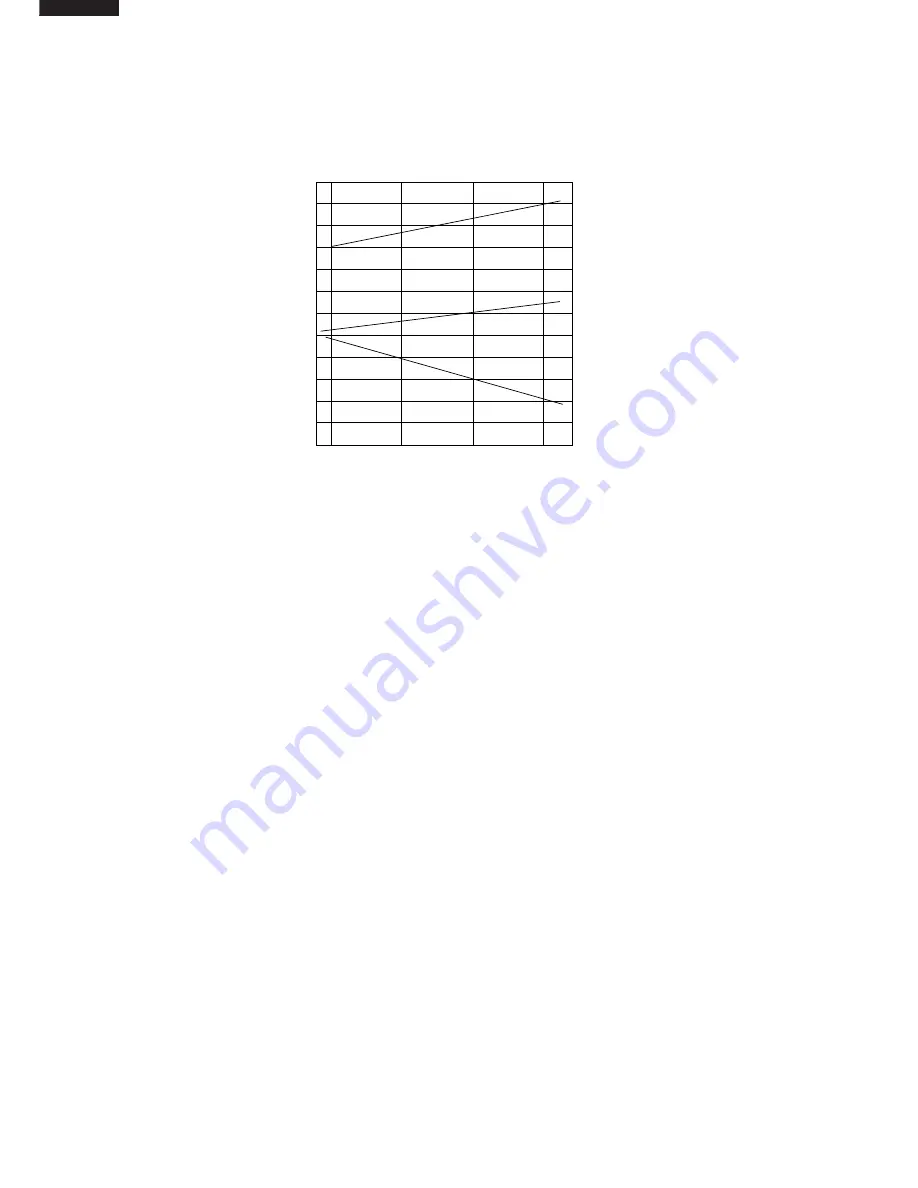
At Cooling for AH-

MX122 / AH-MX152

25

30

35

40

2.4

2.6

2.8

3.0

3.2

12

14

16

700

800

900

1000

(Running frequency: 77Hz)

Cooling capacity(kW)

Outside air temp.(˚C)  

Input(W)

Outlet air temp.(˚C)

Summary of Contents for AH-MX122

Page 1: ...ndition and only parts identical to those specified should be used SERVICE MANUAL Page SPECIFICATIONS 2 EXTERNAL DIMENSIONS 3 WIRING DIAGRAMS 5 ELECTRICAL PARTS 7 BLOCK DIAGRAM 8 MICROCOMPUTER CONTROL SYSTEM 9 FUNCTIONS 13 FUNCTION AND OPERATION OF PROTECTIVE PROCEDURES 17 BREAKDOWN DIAGNOSIS PROCEDURE 19 REFRIGERATION CYCLE 21 PERFORMANCE CURVES 22 DISASSEMBLING PROCEDURE 23 REPLACEMENT PARTS LIS...

Page 2: ...ype Control Capillary tube Refrigerant volume 50g 740g 50g 800g Noise level High dB A 36 43 40 48 at cooling Med dB A 32 43 35 48 Low dB A 27 43 29 48 Fan system Drive Direct drive Air flow quantity High m3 min 9 8 30 10 5 30 at cooling Med m3 min 8 8 30 9 5 30 Low m3 min 6 4 30 6 6 30 Fan Cross flow fan Propeller fan Cross flow fan Propeller fan Connections Refrigerant coupling Flare type Refrige...

Page 3: ...ENSIONS INDOOR UNIT OUTDOOR UNIT Length unit mm 19 5 58 CRMC A442JBE0 R03 AAA 2PCS SHARP CORPORATION INVERTER AIR CONDITIONER 182 815 278 198 1100 269 179 5 182 5 136 81 780 70 540 310 335 540 12 37 5 4 5 58 158 16 ...

Page 4: ...ON DIMENSIONS 815 unit size More than 50mm E Center of wall hole Leftward piping Center of wall hole Backward piping Outline of indoor unit 55 95 80 55 A J I F E D D F A C J H I G B 21 278 unit size 38 Ceiling E ...

Page 5: ...UE 5 3 1 N BLACK FAN MOTOR BLUE RED COMPRESSOR FAN MOTOR UNIT TO UNIT CORD CONTROL BOARD UNIT N 1 1 1 N N 2 2 R P M SIGNAL INTERNAL THERMAL FUSE LED INDICATION FOR SELF DIAGNOSIS Abnormal contents Temperature Indicator Blinking No 1 2 3 4 5 6 7 14 17 18 19 Short circuit of the outdoor thermistor Overheat of the compressor Abnormal AC current Compressor lock Open circuit of the outdoor thermistor A...

Page 6: ...Electronic Control Circuit Diagram for AU MX122 ...

Page 7: ...Electronic Control Circuit Diagram for AU MX152 ...

Page 8: ...model select Outdoor ratings Wireless preheat Indoor outdoor control signal I O Outdoor unit power supply on off control LED display Test run forced operation Auxiliary mode button ON OFF Self diagnostics fault diagnosis Unit unit wiring AC power and serial signals CPU 15 A protection Outdoor fan 4 way valve Power transistor module Compressor Current transformer Compressor thermistor Heat exchange...

Page 9: ... 7K 50V 1000p 1000p 50V P37 P44 P46 P47 4 3 2 1 7 6 5 8 1 1K FUSE THERMAL SSR1 470 1 8K 16 9 10K 3 1 POWER SUPPLY SINGLE PHASE 2 1 JP10 33K R2 TRANS1 D1 4 33K R3 C4 50V 0 1µ 7812 IC2 35V C3 1000µ IN 0 1µ 25V OUT C5 47µ 25V 100 1 2W R1 JP11 C6 25V 47µ 0 1µ 25V C7 IN IC3 D5 7805 25V 0 1µ R31 IC4 8 NC 9 1 18 13 11 C31 250V 0 01µ SSR1 CNR1 L1 430V C1 2µ FUSE THERMAL MOTOR FAN 5 3 1 CN1 C32 C33 680 R6 ...

Page 10: ...1 RY1 IC3 WPE1 3A 250V BLACK C4 C30 ZD1 JP99 R32 JP9 C8 JP28 D5 IC3 C6 R1 JP11 TRANS1 Q1 R3 R2 C3 CN8 1 1 2 3 3 8 IC7 C33 JP10 CN9 JP30 C13 R21 JP25 R38 2 3 3 D7 R63 C28 R57 3 4 1 2 JP14 TERMINAL BOARD TERMINAL BOARD JP13 BROWN IN OUT S RED N BLUE L1 SSR1 1 CN1 FAN M 5 JP12 CNR1 FAN M CN6 R23 R 6 6 R 6 7 R 6 2 R 6 1 R 6 0 R 5 9 D9 D8 1 D2 D4 D1 D3 C1 3 L GND 12V 24V 5V BCN201 C202 C201 1 3 IC201 F...

Page 11: ...26 16V 10 F 5V C22 16V 10 F C21 16V 10 F R21 6 8K F R20 6 8K F C15 10V 220µF R10 6 8K F R8 2 7K F R9 1 00K F D2 1 2 3 1 2 3 5V C23 50V 1µF PST 993D IC3 OSC1 10MHz 5V 5V C17 10V 100µF 2 1 F R46 10K JP1 R34 10K NC NC 5V 33 34 35 36 37 38 39 40 41 42 43 44 45 46 47 48 49 50 51 52 53 54 55 56 57 58 59 60 61 62 63 64 32 31 30 29 28 27 26 25 24 23 22 21 20 19 18 17 16 15 14 13 12 11 10 09 08 07 06 05 04...

Page 12: ...26 16V 10 F 5V C22 16V 10 F C21 16V 10 F R21 6 8K F R20 6 8K F C15 10V 220µF R10 6 49 F R8 1 8K F R9 1 00K F D2 1 2 3 1 2 3 5V C23 50V 1µF PST 993D IC3 OSC1 10MHz 5V 5V C17 10V 100µF 2 1 F R46 10K JP1 R34 10K NC NC 5V 33 34 35 36 37 38 39 40 41 42 43 44 45 46 47 48 49 50 51 52 53 54 55 56 57 58 59 60 61 62 63 64 32 31 30 29 28 27 26 25 24 23 22 21 20 19 18 17 16 15 14 13 12 11 10 09 08 07 06 05 04...

Page 13: ...D 2 FROM TERMINAL BOARD 1 FROM CONTROL BOX FROM DIODE BRIDGE DB1 FROM DIODE BRIDGE DB1 FROM PTC1 T5 DB1 BLACK C5 NR2 WPE3 R2 R1 CT1 3A 250V RY1 CNR2 CNR1 RY2 WINTER KIT OPTION T11 GRAY T10 T9 WPE2 20A 250V BLUE YELLOW IPM R33 R32 R31 R30 R29 R28 C10 C40 R52 OUT C45 CN14 1 4 1 CN12 4 IN IC2 C45 JP23 R50 R40 R39 JP1 R46 C33 Q2 Q1 C1 SA1 D7 D6 JP2 JP17 JP19 JP18 4 WAY VALVE CN4 FAN MOTOR CN3 1 3 1 5 ...

Page 14: ...After operation begins 2 minutes running at the h zone of the room temperature is stored in memory and that becomes the set value 3 Circulation The frequency code 0 is sent to the outdoor machine and only the fan of the indoor machine runs the compressor does not run 1 2 Indoor fan control 1 Control for indoor freezing prevention If the temperature of the indoor heat exchanger stays below approxim...

Page 15: ... within the range of 2 C 1 4 ON timer The ON timer is set by pressing the ON timer button In order to attain the set temperature at the set time the operation starting time is corrected by fuzzy computing one hour before the set time 1 5 OFF timer The OFF timer is set by pressing the OFF timer button Operation is as follows 1 9 Full power operation Immediately begins cooling or heating at maximum ...

Page 16: ...in relay is turned off in 8 minutes Although the error is not displayed it is memorized and can be displayed when it is recalled 2 If the operation is stopped and the emergency operation button is pressed down for 5 seconds or more the self diagnosis memory can be recalled 2 OUTDOOR UNIT 2 1 Frequency control 1 AC current peak control 3 Details of self diagnosis error mode are informed by the flas...

Page 17: ...ture of the compressor chamber exceeds 114 C the compressor is stopped In this case the outdoor fan does not stop and when the compressor chamber temperature decreases to 100 C three minutes after operation is stopped another try will be made Three retries are allowed On the fourth retry a complete stop request signal is sent to the indoor unit and the outdoor unit will remain stopped until reset ...

Page 18: ...tely 26A or more flows in the power transistor module Also stops the compressor if the temperature of the power transistor module is exceeds 105 C Lowers the operating frequency if the compressor AC current exceeds 7 5A Stops the compressor if the current exceeds at 40Hz or less set valve Stops the compressor if the compressor AC current exceeds 2 7A immediately after activating the compressor in ...

Page 19: ...f an outdoor thermistor breaks Stops the compressor if if the operating frequency is above 70 Hz and the compressor current is below 1 0 A Turns the compressor relay off if the indoor unit does not receive a serial signal from the outdoor unit for 8 minutes Stops the compressor if the outdoor unit does not receive a serial signal from the indoor unit for 30 seconds During compressor operation Duri...

Page 20: ... the outdoor control board assembly Current transformer wire break 1 Reattach 2 Replace the outdoor thermistor assembly 1 Replace the outdoor thermistor assembly 1 Clear the discharge outlet 2 Assure power supply voltage 3 Refill to rated amount 4 Replace the outdoor ther mistor assembly 5 Replace the indoor control board assembly or only TH2 1 Apply an external shock to the compressor 2 Replace t...

Page 21: ...tor Compressor thermistor Heat exchanger pipe thermistor Outdoor temp thermistor TH1 TH2 TH3 No 1 to 2 No 3 to 4 Red Orange No 5 to 6 Green Microcomputer terminal Input signal To Outdoor control board Adaptor C14 GND R17 Pin No 43 Pin No 42 0 1 0 Low input 1 High input K Heat exchange thermistor TH2 orange 25 C resistance 15 K Room temperature thermistor TH1 yellow 25 C resistance 10 K 25 C resist...

Page 22: ...sure MPaG 102 C 40 C 13 C 12 C 0 45 101 Cool Max Cool 70 C 42 C 14 C 10 C 0 63 50 settle No Hz Dimension of Capillary tube Model ø2 7 ø1 5 400 O D I D L Capillary tube REFRIGERATION CYCLE Refrigeration Cycle for AH MX122 AH MX152 1 2 Capillary tube 3 Outdoor unit Condenser Evaporator Indoor unit Compressor Flare coupling Flare coupling Silencer 4 3 way valve 2 way valve Accumulator ø2 7 ø1 6 300 O...

Page 23: ...ustment louver 45 Horizontal adjustment louver front 3 Indoor air temp Cooling 27 C At Cooling for AH MX122 AH MX152 25 30 35 40 2 4 2 6 2 8 3 0 3 2 12 14 16 700 800 900 1000 Running frequency 77Hz Cooling capacity kW Outside air temp C Input W Outlet air temp C ...

Page 24: ...p Note During reassembly install the holder after installing the front panel This will make it easier to assemble the front panel panel 5 Pull the front panel up 6 Remove the unit to unit wiring from the terminal board 7 Remove a screw fixing the control box cover and remove it 8 Remove a screw fixing the ground wire Note During reassembly take care for the direction of the lead wire 4 Close the o...

Page 25: ...he thermistor holder from the evaporator 12 Remove the display from the drain pan 13 Remove the screw fixing the pipe holder 14 Remove 3 screws fixing the control box and remove the control box 15 Remove a screw fixing the drain pan 16 Pull drain pan toward you CN1 CN6 CN3 CN2 ...

Page 26: ...move 2 screws fixing the motor cover and pull up the fan 21 Loose a screw fixing fan Cautionary points for assembling the fan a When inserting the motor shaft into the metal fan boss take care to prevent injuring the inner surface of the metal fan boss b Before fastening the motor shaft and fan insert the motor shaft into contact with the bottom of the metal fan boss Fan motor Motor shaft Fan boss...

Page 27: ...e guide from the center of the front panel 2 After the left half is inseted completely press the display cover and snap in the 3 hooks on the right How to remove the control box 1 Remove the photo detector unit Press and spread the upper hook and the photo detector unit will be ready for removal 2 Remove the screw fixing the terminal board 3 Remove a screw fixing the cord holder 4 Remove 2 screws ...

Page 28: ...tion turn the drain hose to the state of the engagement position After reinstallation verify that it is securely fastened How to remove the horizontal louver Slightly pull down the hinge area deflect the louver and unhook it from the hinge Remove the shaft from each of the left and right sides Drain pan Drain Hose Groove Projection To disconned To reconnect ...

Page 29: ...oose a screw fixing the side cover 2 Loose the unit to unit cord 3 Loose a screw fixing the cord clamp 4 Loose 4 screws fixing the top panel 5 Loose 6 screws fixing the front panel 6 Cut 2 nylon bands 7 Remove 6 termials Right side view Left side view Right side view Left side view Front view ...

Page 30: ...he terminal cover 9 Remove 3 terminals 10 Loose 4 screws fixing the control box 11 Take out the control box DISASSEMBLING PROCEDURE OF THE FAN 1 Loose the fan nut and fan can take out 2 Fan motor is secured by 4 screws ...

Reviews: