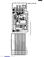
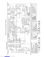
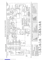
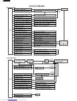


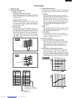


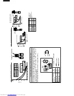


BLOCK DIAGRAMS
INDOOR UNIT
AC power
CPU
3 A
WPE1
DC power supply circuit
Fan motor phase control circuit
Rotation pulse input circuit
AC clock circuit
Louvre motor drive circuit(upper)
Louvre motor drive circuit(lower)
Remote controller signal reception circuit
Buzzer drive circuit
CPU reset circuit
CPU oscillator circuit
Room temp. detect circuit
Heat exchanger pipe thermo circuit
Compensation circuit/ select circuit
Compensation circuit
Switchover circuit
Serial I/O circuit
Compressor relay drive circuit
LED drive circuit
Auto restart circuit
Test run circuit
Auxiliary mode
Power on circuit
Room fan motor
Fan motor pulse detect
Flow direction control (louver motor upper)
Flow direction control (louver motor lower)
Wireless remote control operation
Audible operation confirmation
Room temp. thermistor
Heat exchanger pipe thermistor
Blower temperature, fan speed, model select
Outdoor ratings
Wireless, preheat
Indoor/outdoor control signal I/O
Outdoor unit power supply on/off control
LED display
Test run (forced operation)
Auxiliary mode button ON/OFF
Self diagnostics, fault diagnosis
Unit-unit wiring
(AC power and
serial signals)
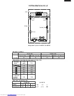
CPU
15 A
protection
Outdoor fan
4-way valve
Power transistor module
Compressor
Current transformer
Compressor thermistor
Heat exchanger pipe thermistor
Outdoor temperature thermistor
Heat exchanger pipe thermistor(option)
Outdoor temperature thermistor(option)
LED
3 A
protection
10 A
protection
Power supply circuit
(built into IPM)
CPU oscillator circuit
Outdoor fan relay drive circuit
4-way valve relay drive circuit
Power transistor module drive circuit
Serial I/O circuit
CPU reset circuit
DC overcurrent detection circuit
AC overcurrent detection circuit
Compressor thermo circuit
Heat exchanger pipe thermo circuit
Outdoor temp. thermo. circuit
Winter kit circuit (option)
LED drive circuit
Test mode circuit
Filter
circuit
Smoothing
circuit
Unit-unit wiring (AC power
and serial signals)
OUTDOOR UNIT


