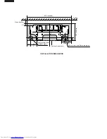
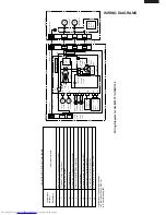

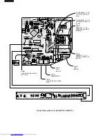

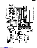
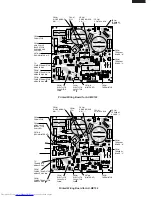

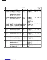

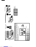
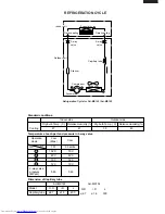


MICROCOMPUTER CONTROL SYSTEM
Electronic Control Circuit Diagram for AH-
MX122
and
AH-MX152
(CN9)
LED101
LED104
LED103
LED102
LED110
LED109
LED108
LED107
LED106
LED105
R101
R102
R103
R104
R105
R106
R107
R108
R109
1/2W
1/2W
1/2W
1/2W
220
220
300
220
220
220
220
220
100
1/2W
1/2W
1/2W
1/2W
1/2W
LED111
1/2W
1/2W
1/2W
330
R114
R40
3.3K
50V
50V
C21
C22
1000p
1000p
BCN3
BCN2
R58~R62
(SW2)
MOTOR
FAN
IC
HOLE
3
2
1
P00
P01
P02
P03
P04
P05
P06
P07
P10
P11
P12
P13
P14
P16
P17
33
34
35
36
37
38
39
40
41
42
43
44
45
46
47
48
52
53
54
55
56
57
58
59
60
61
62
63
64
P63
P64
P65
P66
P67
AVss
Vref
Vcc
P30
P31
P32
P33
P34
51
50
49
P35
P36
P20
P21
P22
32
31
30
P23
P24
P25
P26
P27
Vss
Xout
Xin
P40
P41
RESET
CNVss(Vpp)
P42
29
28
27
26
25
24
23
22
21
20
19
18
17
P62
P61
P60
P57
P56
P55
P54
P53
P52
P51
P50
P45
P43
1
2
3
4
5
6
7
8
9
10
11
12
13
14
15
16
NC
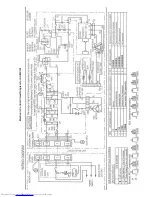
M3803**
IC1
(PATTERN SIDE)
PC2
PC1
4
2
4
3
1
2
4.7K
100K
+
0.047
µ
50V
250V
0.01
µ
680
680
2W
2W
680
680
2W
2W
680
2W
22K
P15
1
10K
10K
0.1
µ
25V
8M
6
5
4
3
2
1
PIPE TEMP.
TH2
10k
Ω
(25˚C)
15k
Ω
(25˚C)
ROOM TEMP.
TH1
C2
0.22
µ
250V
NR1
IN
T
250V
OUTRY1
WPE
N
N
2S
1
UNIT
OUTDOOR
TO
TERMINAL
BOARD
KID65783AP
IC6
10
SW1
5V
GND
12V
-24V
33K
33K
33K
33K
33K
16V
C26
0.01
µ
R41
1.8K
33K
33K
33K
1000P
3
2
3
1
2
R23
3.3K
CN6
100
µ
C8
10V
+
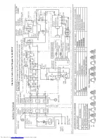
FAN L
FAN M
FAN H
RATE HEAT
TEA
MODEL 5
MODEL 4
MODEL 3
MODEL 2
MADEL 1
R42
R43
R44
R45
R46
R47
R48
R49
R50
R51
R52
R53
R54
R55
R56
JP 1
JP 2
JP 3
JP 4
JP 5
R67
R66
12K
12K
2W
D9
D8
R65
R64
11K
2W
2W
11K
2W
C30
100
µ
35V
C29
ZD1
R63
C28
D7
R57
C27
R38
R37
R36
R35
R34
JP8
JP7
JP6
R30
380
R29
680
C19
+
+
C18
10
µ
16V
16V
10
µ
10K
(F)
R27
10K
(F)
R26
R21
R20
R19
C13
C12
C11
IC7
IC8
OSC1
FRONT
1/2W
R9
R8
C9
C10
1000p
50V
25V
0.1
µ
R5
RY1
R4
BZ1
BUSY
1
12V
2
5V
3
4
CLOCK
5
SERIAL
OE
6
7
RESET
GND
8
HOT KEEP
PREHEAT
WIRELESS
2.7K
50V
1000p
1000p
50V
P37
P44
P46
P47
4
3
2
1
7
6
5
8
1
1K
FUSE
THERMAL
SSR1
470
1.8K
16
9
10K
3
1
POWER
SUPPLY
SINGLE
PHASE
2
1
JP10
33K
R2
TRANS1
D1~4
33K
R3
+
C4
50V
0.1
µ
7812
IC2
35V
C3
1000
µ
IN
0.1
µ
25V
OUT
C5
+
47
µ
25V
100
1/2W
R1
JP11
+
C6
25V
47
µ
0.1
µ
25V
C7
IN
IC3
D5
7805
25V
0.1
µ
R31
IC4
8
NC
9
11
8
13
11
C31
250V
0.01
µ
SSR1
CNR1
L1
430V
C1
2
µ
FUSE
THERMAL
MOTOR
FAN
5
3
1
CN1
C32
C33
680
R6
CN101
22
3
3
1
1
8
8
1
1
22
3
3
44
5
5
66
7
7
CN102
NC
NC
10(B2)
11(A2)
12(F2)
15(B1)
18(F1)
17(G1)
16(A1)
14(CM1)
13(CM2)
9(H2)
8(C2)
7(G2)
6(D2)
5(E2)
4(H1)
3(C1)
2(D1)
1(E1)
H2
H1
CM1,2
D2
G2
A2
E2
F2
B2
C2
D1
G1
A1
C1
B1
E1
F1
33K
33K
R33
R32
JP9
JP99
TEST
POWE ON
R39
20K
C24
16V
0.01
µ
1
3
2
C25
50V
1000P
330
W115
1/2W
LED121
R116
330
1/2W
1/2W
R111
330
R112
R110
330
330
1/2W
R113
330
25V 0.1
µ
680
680
Q1
Q2
R68
R69
3A
33K
CN7
0.1
µ
25V
33
µ
10V
+
5V
GND
C201
C202
IC201
BCN201
BCN1
11
33
2
2
6.8K
8
IC5
9
1
16
10K
R7
CN3
1
2
3
4
5
LOUVER
MOTOR
UPPER
LOWER
LOUVER
MOTOR
4
5
1
CN2
2
3
∆
:TEST POINT
(NOTE)
LED101 : OPERATION
LED102 : TIMER
LED103 : ROOM TEMP.
LED104 : OUTDOOR TEMP.
SW1 : AUX.(TEST RUN)
SW2 : POWER SELECTION
LED105 : POWER MONITOR ECO
LED106 : POWER MONITOR 1
LED107 : POWER MONITOR 2
LED108 : POWER MONITOR 3
LED109 : POWER MONITOR 4
LED110 : POWER MONITOR POWER
HL
50V
C34
JP34
C17
16V
0.01
µ
JP23
680
NONE
USE
SW2
USE
NONE
NONE
NONE
NONE
NONE
USE
15K
13K
13K
15K
15K
13K
13K
15K
13K
NONE
NONE
USE
NONE
NONE
NONE
NONE
USE
USE
NONE
NONE
NONE
NONE
USE
NONE
NONE
13K
15K
13K
13K
15K
15K
13K
13K
15K
USE
NONE
NONE
NONE
NONE
USE
USE
15K
13K
13K
15K
15K
13K
13K
15K
13K
NONE
NONE
USE
NONE
NONE
NONE
NONE
NONE
NONE
NONE
NONE
NONE
NONE
NONE
USE
USE
NONE
NONE
NONE
13K
24K
15K
13K
13K
15K
15K
13K
13K
130K
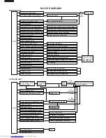
AH-
MX122
AH-
MX152
AH-X10BE
AY-X08BE
A
H
-
MX152
A
H-MX122
MODEL
JP1
JP2
JP3
JP4
JP5
JP6
JP7
JP8
JP9
R51
R50
R49
R48
R47
R46
R45
R44
R43
R42
JP99
68
K
13K
13K
15K
15K
13K
13K
----
47
K
13K
NONE
USE
USE NONE USE NONE
NONE
USE
NONE
NON
E
33
K
13K
13K
2.4
K
3.6
K
13K
----
- 1
5K
15K
13K
USE
NONE
USE NONE
USE
NONE
NONE
NONE


