


35
AH-N45DP2
AU-N45DP2
AH-N56DP2
AU-N56DP2
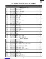
REF. NO.
PART NO.
DESCRIPTION
Q'TY
CODE
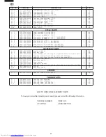
HOW TO ORDER REPLACEMENT PARTS
To have your order filled prompty and correctly, please furnish the following information.
1. MODEL NUMBER
2. REF. NO.
3. PART NO.
4. DESCRIPTION
SCREWS, NUT AND BOLT
6- 1
LX-BZA072JBE0
Special screw
4
AB
6- 2
LX-NZ0128JBE0
Special nut
1
AB
6- 3
LX-BZA140JBE0
Special screw
24
AB
6- 4
LX-BZA292JBE0
Special screw
19
AC
6- 5
LX-BZA166JBE0
Special screw
1
AB
6- 6
LX-NZA048JBE0
Special nut
4
AA
6- 7
XCPSD40P25000
Tapping screw
1
AC
6- 8
XCTSD40P12000
Tapping screw [AU-N45DP2]
2
AA
6- 8
XCTSD40P12000
Tapping screw [AU-N56DP2]
4
AA
6- 9
XCTSD40P40000
Tapping screw
2
AA
6-10
LX-BZA075JBE0
Special screw
1
AA
PACKING PARTS
7- 1
CPADBA050JBKZ
Bottom pad assembly
1
AM
7- 2
CPADBA051JBKZ
Packing pad assembly
1
AM
7- 3
SPAKCB322JBEZ
Packing case [AU-N45DP2]
1
AX
7- 3
SPAKCB323JBEZ
Packing case [AU-N56DP2]
1
AX


