background image

1

AH-S22AW2
AH-S25AW2

SY994AHS25AW2

SERVICE MANUAL

SHARP CORPORATION

AU-S22AW2
AU-S25AW2

OUTDOOR UNIT

Page

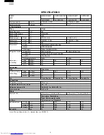
SPECIFICATIONS ............................................................................................................................................  2
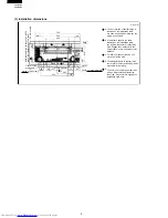
EXTERNAL DIMENSIONS ................................................................................................................................. 3
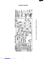
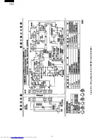
WIRING DIAGRAMS .........................................................................................................................................  5
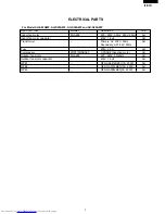
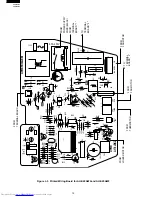
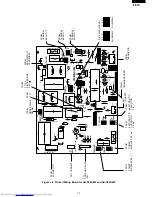
ELECTRICAL PARTS ........................................................................................................................................ 7
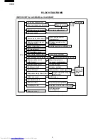
BLOCK DIAGRAM ............................................................................................................................................. 8
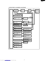
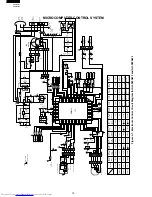
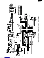
MICROCOMPUTER CONTROL SYSTEM ....................................................................................................... 10
FUNCTIONS .................................................................................................................................................... 14
FUNCTION AND OPERATION OF PROTECTIVE PROCEDURES ...............................................................  19
BREAKDOWN DIAGNOSIS PROCEDURE ....................................................................................................  21
REFRIGERATION  CYCLE .............................................................................................................................  23
PERFORMANCE CURVES ............................................................................................................................  24
DISASSEMBLING PROCEDURE ...................................................................................................................  25
PUMP DOWN ....................................................................................................................................................34
REPLACEMENT PARTS LIST ......................................................................................................................... 35

TABLE OF CONTENTS

SPLIT TYPE

ROOM AIR CONDITIONERS

INDOOR UNIT

MODELS

AH-S22AW2
AH-S25AW2

In the interests of user-safety (Required by safety regulations in some
countries)  the set should be restored to its original condition and only
parts identical to those specified should be used.

Summary of Contents for AH-S22AW2

Page 1: ...RATION OF PROTECTIVE PROCEDURES 19 BREAKDOWN DIAGNOSIS PROCEDURE 21 REFRIGERATION CYCLE 23 PERFORMANCE CURVES 24 DISASSEMBLING PROCEDURE 25 PUMP DOWN 34 REPLACEMENT PARTS LIST 35 TABLE OF CONTENTS SPLIT TYPE ROOM AIR CONDITIONERS INDOOR UNIT MODELS AH S22AW2 AH S25AW2 In the interests of user safety Required by safety regulations in some countries the set should be restored to its original conditi...

Page 2: ...ooved tube type Control Capillary tube Refrigerant volume 630g 660g Noise level High dB A 35 43 36 43 at cooling Med dB A 31 32 Low dB A 26 27 Fan system Drive Direct drive Air flow quantity High m3 min 7 0 23 1 7 2 23 1 at cooling Med m3 min 6 1 6 2 Low m3 min 4 7 4 9 Fan Cross flow fan Propeller fan Cross flow fan Propeller fan Connections Refrigerant coupling Flare type Refrigerant tube size Ga...

Page 3: ...INDOOR UNIT Figure E 2 OUTDOOR UNIT AU F22SEY 250 280 304 470 10 5 38 58 5hole 185 35 85 135 515 530 15 698 129 Length mm AY F22SE 750 270 183 1500 Length unit mm 19 5 58 CRMC A442JBE0 R03 AAA 2PCS FULL POWER SHARP CORPORATION INVERTER AIR CONDITIONER 182 ...

Page 4: ...5 shift the center down by 3 mm and makle a hole C C The triangular dents 2 places in the center are for center positioning which are usable for installing D The hole in the center upper part has shape After tentatively tightening the screw it is possible to ergage the installation plate here E Unit mm Installation dimension range 395 to 550 when the installation angle is used 50 mm or more 29 45 ...

Page 5: ...5 AH S22AW2 AH S25AW2 WIRING DIAGRAMS Figure W 1 Wiring Diagram for AH S22AW2 and AH S25AW2 ...

Page 6: ...6 AH S22AW2 AH S25AW2 Figure W 2 Wiring Diagram for AU S22AW2 and AU S25AW2 ...

Page 7: ...door fan motor capacitor 430V 1 5µF AH Transformer Primary AC 230V 50Hz AH Secondary AC14 6V 50Hz Fuse 250V 2 5A AH Compressor 2RD110N5BA03 3 PHASE Induction motor AU Outdoor fan motor MLA485 220 240V 50 60Hz AU Outdoor fan motor capacitor 430V 1 5µF AU WPE1 QFS AA047JBE0 13A 250V AU WPE2 QFS GA015JBE0 10A 250V AU WPE3 QFS GA008JBE0 3A 250V AU ELECTRICAL PARTS ...

Page 8: ... Serial I O circuit Compressor relay drive circuit LED drive circuit Auto restart circuit Test run circuit Power on circuit Flow direction control louvre motor Wireless remote control operation Audible operation confirmation Room fan motor Fan motor pulse detect Room temp thermistor Heat exchanger pipe thermistor Blower temperature fan speed model select Outdoor ratings Wireless preheat Indoor out...

Page 9: ...drive circuit Power supply circuit built into IPM CPU oscillator circuit AC overcurrent detection circuit DC overcurrent detection circuit LED Heat exchanger pipe thermistor Compressor thermistor Current transformer Compressor Power transistor module Outdoor fan Smoothing circuit Filter circuit Unit unit wiring AC power and serial signals 13 A protection Outdoor temp thermo circuit Outdoor tempera...

Page 10: ...Z 12V 12V 12V SSR1 CN101 CN1 PHOTO DETECTOR UNIT AUX TEST RUN YELLOW LED102 RED LED101 IC101 2 3 CN3 2 3 4 5 CN301 CN4 LOUVER MOTOR FUNCTION MODEL 1 fmin UP ON OFF MODEL 2 THERMO SHIFT ON OFF MODEL 3 AH AY MODEL 4 fmax DOWN ON OFF MODEL 5 OUT T THERMO ON OFF MODEL 6 07 09 MODEL 7 HOT KEEP ON OFF WIRELESS CHANGE ON OFF PREHEAT OFF ON RATE COOL RATE HEAT FAN L SPEED FAN M SPEED FAN H SPEED IC1 PIN N...

Page 11: ...K 1000P C14 R4 3 3K C13 0 1µ 25V C12 4700P 250V IC3 C23 1µ 50v OSC1 5V PST993D 2W 680 2W 680 2W 680 2W 680 2W 680 13V Q3 D8 MRY1 Q1 D6 RY1 50V R5 56K PC2 R11 R12 R13 R14 R15 4 3 4 3 1 2 1 2 5V 5V R17 10K 10K R16 PC1 PC817X7 D1 B C16 0 1µ 25v C20 100µ 10v A 5V 5V 5V 13V R46 10K JP1 F OUTPUT R18 47 1W C11 0 1µ 25v C30 100µ 25v IC2 7805 10 9 8 7 6 5 4 3 2 1 APM VCC1 VIN1 GND U X V Y W Z 1 2 3 4 CN11 ...

Page 12: ... C18 RED D7 R24 C3 C4 C6 C5 ZD1 ZD1 R3 CN9 TR R4 R5 R7 5 1 C101 LED102 LED101 C102 CN101 GND VCC VOUT IC101 R30 R31 F L F M F H R35 R33 R37 R39 RATE C RATE H R32 R34 R36 R38 JP12 JP5 JP6 JP7 JP8 JP9 PREHEAT WIRELESS HOT KEEP 07 09 OUT TH C15 R19 R7 C8 R6 R20 R21 R80 JP25 C7 3 Q1 4 1 5 6 IC80 JP4 C17 JP3 JP2 TH SHIFT AH AY fmax JP1 fmin C80 R12 C9 JP99 D5 R22 JP26 JP27 JP11 R10 R11 CN1 5 C12 C11 16...

Page 13: ...2 1 9000 BTU HP R3 R9 D2 LED1 JP12 JP8 C10 R39 R40 OUT R10 R1 R2 C1 IN MRY1 R8 1 4 WINTER KIT OPTION JP18 C17 C18 R35 R46 JP1 R34 C30 RY1 NR2 C5 CNR1 R33 R30 R32 R29 R31 R28 IC2 C11 R18 JP4 JP5 JP6 Q3 D8 E C B E C B D6 JP2 10 1 CN11 R41 IPM 1 5 CN3 FAN MOTOR Q1 JP11 JP10 JP9 JP14 JP13 JP19 C23 JP17 6 1 R20 R38 C21 R21 C22 R11 C26 5V GND QPWBFB251JBE0 1 2 3 4 AU S22AW2 T10 T9 BLUE IPM YELLOW T11 T5...

Page 14: ... four minutes during cooling or dry this control stops the compressor Over 2 C the compressor will run again 2 Indoor fan and operating frequency The indoor fan has 12 speeds and changing is done in four stages Auto High Med and Low The relations between the indoor fan speed air quantity setting operating frequency and indoor heat exchanger are shown in the following charts 1 INDOOR UNIT 1 1 Tempe...

Page 15: ...wing louvre The louvre is moved by a stepping motor to perform swing and fixing in the set position If the FLOW DIRECTION button is prossed during swing it will stop If the FLOW DIRECTION button is prossed while it is stopped it will swing 1 7 Restart control Once the compressor stops this control prevents it from starting again for 3 minutes It also prevents starting for 20 seconds immediately fo...

Page 16: ...mpressor relay goes off the compressor relay will stay on ON ON OFF ON OFF Air conditioner operation Compressor relay 150 sec 30 sec ON ON OFF ON ON Air conditioner operation Compressor relay 150 sec 1 12 Auto Restart When power failure occures after power is recovered the unit will automatically restart in the same setting which were active before the power failure Operating mode Cool Dry Tempera...

Page 17: ...very 60 seconds and normal operation is restored If the temperature of the indoor heat exchanger goes down to approximately 0 C and this condition continues for 4 minutes the compressor is stopped When the temperature rises above approximately 2 C normal operation is restored 2 2 Overcurrent protection 1 Compressor lock detection If the set value 3 0 A of AC current is exceeded at 10 to 30 Hz when...

Page 18: ... On the fourth retry a complete stop request signal is sent to the indoor unit and the outdoor unit will remain stopped until reset is performed At this time the 3 minute delay for control of the outdoor unit will not function therefore do not cancel by removing the plug and cutting the power 2 5 Serial signals 1 Serial signals consist of all 96 bit signals 2 If the outdoor unit does not receive a...

Page 19: ... current exceeds at 40Hz or less set valve Stops the compressor if the compressor AC current exceeds 3A immediately after activating the compressor at 10 to 30Hz Lowers the operating frequency if the temperature of the compressor chamber thermistor TH1 rises above 105 C Stops the compressor if the thermistor stays above 105 C for 1 minutes at 35Hz or less Stops the compressor if the compressor cha...

Page 20: ...off if the indoor unit does not receive a serial signal from the outdoor unit for 8 minutes Stops the compressor if the outdoor unit does not receive a serial signal from the indoor unit for 30 seconds Stop operation The reason that the fuse operation is by connecion error at the inside of terminal board Stop operation The reason that the fuse operation is by connecion error at the inside of termi...

Page 21: ...ure the resistance of thermistor TH2 and TH3 on the outdoor unit see Figure 2 1 Replace power transistor module 1 Clear the discharge outlet 1 Replace the terminal board 1 Rewire 1 Rewire Indoor fan out of order 1 Is the fan motor locked 2 Is the wiring connector firmly fitted 3 Is the speed signal applied to the motor Overheat of the comp ressor error protector operating or outdoor compressor the...

Page 22: ... C Temperature C Tester Tester Thermistor To measure the resistance first remove the connector from the board Color No Connector Compressor thermistor Heat exchanger pipe thermistor Outdoor temp thermistor TH1 TH2 TH3 No 1 to 2 No 3 to 4 Red Orange No 5 to 6 Green Microcomputer terminal Input signal To Outdoor control board Adaptor C14 GND R17 Pin No 43 Pin No 42 0 1 0 Low input 1 High input K Hea...

Page 23: ...e Dry bulb Temp C Relative Humidity 35 40 Temperature at each part and pressure in 3 way valve AU S22AW2 and AUS25AW2 Operation mode Cool Max Cool 1 2 3 4 3 way valve pressure MPaG 92 C 40 C 10 C 5 C 0 46 71 C 42 C 12 C 9 C 0 56 90 60 settle No Hz Operation mode Cool Max Cool 1 2 3 4 3 way valve pressure MPaG 96 C 40 C 12 C 4 C 0 47 66 C 42 C 14 C 10 C 0 58 94 60 settle No Hz Capillary tube O D I ...

Page 24: ... 1200 Cooling capacity kcal h Outside air temp C Input W Outlet air temp C 1 Indoor fan speed Hi 2 Vertical adjustment louver 45 Horizontal adjustment louver front 3 Indoor air temp 27 C NOTE Running frequency 90HZ 25 30 35 40 2200 2400 2600 2800 10 12 14 800 1000 1200 1400 Running frequency 94Hz Cooling capacity kcal h Outside air temp C Input W Outlet air temp C ...

Page 25: ...er or nail etc b Insert the flat tipped screwdriver or nail etc into the lower clearance and pull and lift it toward you for removal 4 Remove one inner screw Note During reassembly don t tighten the screw strongly or it will become idle 5 Remove the fastening screw which retains the cable and remove the cord Note During reassembly install the holder after installing the front panel This will make ...

Page 26: ... to the cabinet When pressing it in take care to prevent the top of the blow out port of the drain pan from being caught by the front panel 9 Remove the control box cover Holding its bottom pull and disengage the upper hook toward the bottom 7 Remove the unit to unit wiring from the terminal board Loosen the screw with the screwdriver and pull out the wiring 8 Remove one fastening screw from the c...

Page 27: ...Remove the fastening screws of the drain pan Two screws on the left side 14 Remove two connectors of the fan motor and one of louver motor 17 Turn the cap area of the drain hose counterclockwise and remove it from the drain pan During installation turn the drain hose to the state of the engagement position After reinstallation verify that it is securely fastened Drain hose Drain pan Groove Project...

Page 28: ...f it is tried to remove the fan alone it will damage the inner surface of the metal fan boss to prevent removing the fan 21 Loosen the fan fastening screw and remove the fan Cautionary points for assembling the fan a When inserting the motor shaft into the metal fan boss takecaretopreventinjuringtheinnersurface of the metal fan boss b Before fastening the motor shaft and fan insert the shaft into ...

Page 29: ... from the cabinet pulling it toward you 3 Remove the thermistor holder from the control box How to remove the electric control box 1 Remove the indicator assembly Press and spread the upper hook and the indicator will be ready for removal 2 Remove the fastening screw of the terminal board 4 Remove the board fastening screws 5 Pull out the board the angle of transformer ...

Page 30: ...ver and remove it at one place Remove the shaft from each of the left and right sides Drain pan and related How to remove the gear box assembly Remove two screws which fasten the gear box assembly Note When installing the gear box assembly fit it aligning the notch shape of the groove of the vertical adjusment louver ...

Page 31: ...to unit wiring from the terminal board 4 Remove 11 screws which fasten the rear panel assembly Even though the rear panel assembly is not removed most of the services are possible 5 Cut the tie band 1 place 2 Free the front panel assembly Remove 2 screws from each of the right and left sides and one screw from the front side 3 Remove the front panel assembly Pulling the bottom toward you disengage...

Page 32: ... the motor angle for removal During reassembling treat the lead wire to prevent it from being in contact with the propeller fan 7 Remove 2 fastening screws of the control box 10 Remove 3 motor fastening screws and remove the motor 11 Remove the bulk head Remove 2 fastening screws Lifting the bulk head remove 2 inner hooks 12 Remove 4 screws which fasten the reactor on the bulkhead and remove the r...

Page 33: ...lacingthePowerFactorModule Power Transistor Module or Diode Bridge 1 The screws should be firmly tightened at the torque of 8 to 10 kg f cm 78 4 to 98 N 2 For the Power Transistor Module or Diode Bridge the silicon grease should be evenly applied between it and radiator plate 14 Remove the thermostat of the heat exchanger Heat exchange pipe thermistor Heat exchange pipe thermistor fixed position 4...

Page 34: ... closed position 6 Keep running the air conditioner for 40 60 seconds When the pressure of the compound gauge reads 0 05MPa then immediately fully close the stop valve opf 3 way side 7 Disconnect the hose and attach the service port cap as it was before Cautions If you run the air conditioner until the pressure drops below 0 05MPa Indoor unit side become negative pressure As a result moisture or d...

Page 35: ... GWAK A203JBFC Front panel 1 AT 1 32 PCOV A306JBF0 Drain cover 1 AE 1 33 TLABCB300JBR0 Wiring diagram 1 AD 1 34 QW VZC500JBE0 Louver motor wire 1 AF 1 35 QW VZC406JBE0 Fan motor wire 1 AK 1 36 GWAK A209JBFA Air purifier frame 2 AH 1 37 PSEL B948JBE0 Aluminum tape 1 AC 1 38 PSEL B947JBE0 Aluminum tape 1 AC CONTROL BOX 2 1 PBOX A191JBF0 Control box 1 AP 2 2 PSEL B558JBE0 Aluminum tape 1 AB 2 3 LHLD ...

Page 36: ...crew cover 2 AC 4 3 LHLD A281JBFA Cord holder for covering the terminal board of indoor unit 1 AC 4 4 XTTSD40P20000 Tapping screw for fixing the cord holder 1 AA 4 5 LX NZ0247JBE0 Special nut for fixing long screw steadily 7 AB 4 6 UBATUA027JBE0 Battery pack 1 AE 4 7 PPLTNA043JBW0 Mounting plate 1 AF 4 8 XTTSD45P30000 Long screw 6 AA 4 9 TINSCA021JBR0 Operation manual 1 AF 4 10 TINS A629JBR0 Insta...

Page 37: ... 3 3 5 3 4 5 1 1 32 2 3 2 10 2 8 2 2 2 12 2 5 4 3 4 12 4 13 2 6 2 9 2 11 2 7 1 6 1 20 1 9 1 8 1 17 1 16 1 15 1 19 1 34 1 18 1 10 1 11 1 12 1 3 1 5 1 1 1 30 1 2 1 7 1 36 1 36 1 25 1 25 1 31 1 33 1 38 1 28 1 27 1 23 1 22 1 21 1 24 4 2 4 2 1 35 4 1 4 1 1 4 1 2 1 37 2 38 4 9 4 10 2 1 2 23 2 4 2 18 1 14 1 13 FU LL PO WE R INV ERT ER AIR CON DIT ION ER ...

Page 38: ...eactor DB2 1 AF 1 33 QW VZD423JBE0 Lead wire Reactor C6 1 AF 1 34 QW VZD424JBE0 Lead wire DB1 C6 1 AE 1 35 QW VZD425JBE0 Lead wire CB C6 1 AE 1 36 QW VZD426JBE0 Lead wire DB1 C8 1 AE 1 37 QW VZD427JBE0 Lead wire C6 DB2 N 1 AF 1 38 RFIL A064JBE0 Ferrite core FC1 FC7 2 AF 1 39 RH IXA584JBEZ Microcomputer IC1 1 AX 1 45 RIC A022BDE0 Integrated circuit IC2 1 AE 1 40 RH IZA140JBE0 Integrated circuit IC3...

Page 39: ...6JBE0 Bonnet 2 AF 3 6 DVLV A302JBK0 2 way valve unit 1 BA 3 7 LX NZA002JBE0 Special nut 1 AA 3 8 GLEG A073JBE0 Compressor cushion 3 AD 3 9 PSPF A686JBE0 Compressor cover 1 AY 3 10 PSPF A685JBE0 Sound proof cover 1 AL 3 11 PSEN A004JBK0 Flare nut assembly H 1 AE 3 12 PSEN A005JBK0 Flare nut assembly L 1 AG 3 13 PCMPRA312JBE0 Compressor 1 CP 3 14 PSPF A718JBE0 Compressor cover 1 AK 3 15 PSPF A719JBE...

Page 40: ...in Japan 2 3 2 26 2 4 2 14 2 1 2 2 2 29 2 21 2 19 2 28 1 1 2 18 4 10 2 13 3 15 3 4 3 3 4 2 4 2 2 9 2 23 2 8 3 9 3 14 3 10 2 10 2 10 2 22 2 11 1 16 1 51 3 2 4 4 2 6 2 24 2 12 2 7 2 15 2 27 1 6 1 8 1 9 4 4 1 50 2 5 1 19 1 5 1 18 3 16 3 17 3 7 2 25 1 4 1 10 1 14 1 12 1 13 1 31 1 15 1 11 1 3 1 38 3 8 3 13 4 5 3 1 2 16 1 17 3 11 3 12 3 6 3 6 3 6 3 18 ...

Reviews: