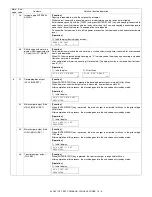
AL-1651CS ADJUSTMENTS 9 - 2
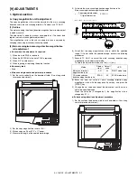
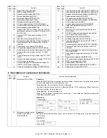
2) Set the copy magnification ratio to 100%.
3) Make a copy on A4 or 81/2" x 11" paper.
4) Measure the length of the copied scale image.
5) Calculate the sub scanning direction copy magnification ratio
using the formula below.
6) Check that the actual copy magnification ratio is within the
specified range. (100 ± 1.0%).
If it is not within the specified range, perform the following
procedures.
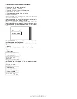
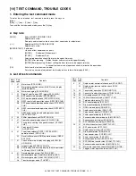
7) Execute TC 48-01 to select the sub scanning direction copy
magnification ratio adjustment mode.
To select the adjustment mode, use the [
←
/
→
] key. (SCAN mode
lamp ON)
8) Enter the new set value of sub scanning direction copy
magnification ratio with the copy quantity set key, and press the
[START] key.
Repeat procedures 1) - 8) until the sub scanning direction actual copy
magnification ratio in 100% copying is within the specified range.
When the set value is changed by 1, the magnification ration is
changed by 0.1%.
B. Image position adjustment
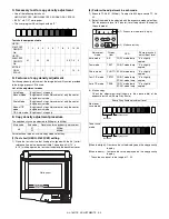
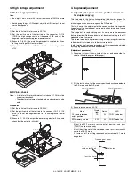
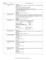
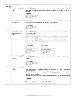
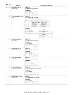
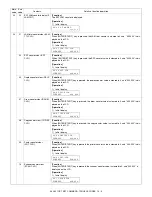
The employed test commands and the contents are as follows:
The modes can be selected by pressing [
←
/
→
] key.
(*): Support for the installation models. For non-installation models,
skip.
* In the 2nd print center offset adjustment, print is made forcibly as
1to2/Long Edge from OC regardless of duplex setting.
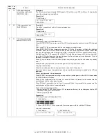
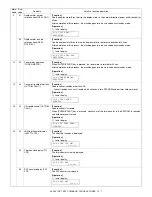
(1) Lead edge adjustment
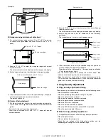
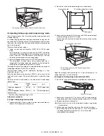
1) Set a scale to the center of the paper lead edge guide as shown
below, and cover it with B4 or 8 1/2" x 14" paper.
2) Execute TC 50 - 01
3) Set the print start position (A: COPY mode lamp ON), the lead
edge void amount (B: PRINT mode lamp ON), the scan start posi-
tion (C: SCAN mode lamp) to zero, and make a copy of the scale
at 100%.
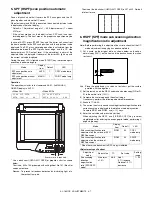
4) Measure the image loss (Rmm) of the scale.
Set C = 10 x R (mm). (Example: Set to 40.)
When the value of C is increased by 10, the image loss is
decreased by 1mm. (Default: 50)
5) Measure the distance (Hmm) from the paper lead edge to the
image print start position.
Set A = 10 x H (mm). (Example: Set to 50.)
When the value of A is increased by 10, the image lead edge is
moved to the paper lead edge by 1mm. (Default: 50).
6) Set the lead edge void amount to B = 50 (2.5mm). (Default: 50)
When the value of B is increased by 10, the void is extended by
about 0.1mm. (For 25 or less, however, the void amount is
regarded as 0.)
* The SFP adjustment is made by adjusting the SPF image scan start
position after OC adjustment.
=
Copy image dimensions
X 100 (%)
Original dimension
Mode
Display
item
Default
LED
TC
Print start position
(Main cassette paper
feed)
TRAY1
50
COPY mode lamp
Main cassette
lamp
50-01
(*) Print start position
(2nd cassette paper
feed)
TRAY2
50
COPY mode lamp
2nd cassette lamp
Print start position
(Manual paper feed)
MFT
50
COPY mode lamp
Manual feed lamp
Image lead edge void
amount
DEN-A
50
PRINT mode lamp
Image scan start
position
RRC-A
50
SCAN mode lamp
Image rear edge void
amount
DEN-B
50
COPY mode lamp
PRINT mode lamp
SCAN mode lamp
100
110
120
130
150
140
mm
1/2mm
JAPAN
HARDDENCD
STAINLESS
Shizuoka
100
110
120
130
150
140
mm
1/2mm
JAPAN
HARDDENCD
STAINLESS
Shizuoka
110
10
20
10
20
Original (Scale)
Paper feed
direction
Reference
Comparison point
Copy
Mode
Display
item
Default
LED
TC
Print center offset
(Main cassette paper
feed)
TRAY1
50
COPY mode lamp
Main cassette lamp
50-10
(*) Print center offset
(2nd cassette paper
feed)
TRAY2
50
COPY mode lamp
2nd cassette lamp
Print center offset
(Manual paper feed)
MFT
50
COPY mode lamp
Manual feed lamp
2nd print center
offset (Main cassette
paper feed)
SIDE2
50
PRINT mode lamp
Main cassette lamp

