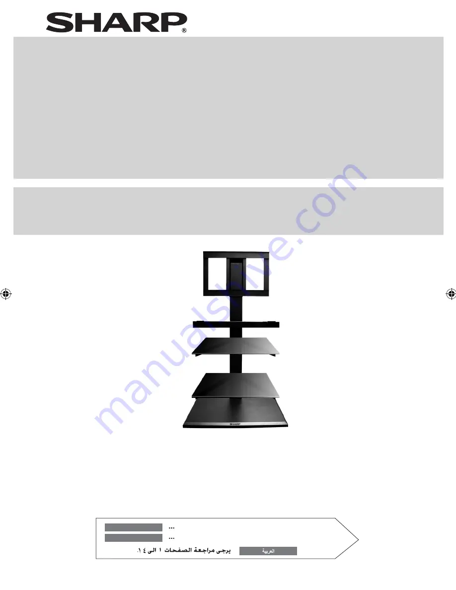
background image

RACK SOPORTE DE PIE

WALL ASIDE STAND

AN-WS350

AN-WS350R

MODELO

MODEL

Please refer to pages E-1 to E-14.

ENGLISH

Consulte las páginas S-1 a S-14 

ESPAÑOL

MANUAL DE MANEJO

OPERATION MANUAL

...

AN-WS350_OM_FRONT.indd   1

2009-08-15   10:37:50

Summary of Contents for AN-WS350

Page 1: ...RACK SOPORTE DE PIE WALL ASIDE STAND AN WS350 AN WS350R MODELO MODEL Please refer to pages E 1 to E 14 ENGLISH Consulte las páginas S 1 a S 14 ESPAÑOL MANUAL DE MANEJO OPERATION MANUAL ...

Page 2: ... W U V METAL BASE x 1 LCD TV SUPPORT A x 2 LCD TV SUPPORT B x 2 LCD U BRACKET x 1 CENTRE BAR x 1 LCD TV HOOK x 2 SOUND BAR SUPPORT x 1 SOUND BAR U BRACKET x 1 SUPPORT PLATE x 1 SCREWS M8 50mm x 4 ALLEN KEY M6 x 1 ALLEN KEY M8 x 1 SOUND BAR SPACER x 8 GLASS SHELF SUPPORT TV SPACER x 4 SCREWS M8 16mm x 4 SCREWS M6 35mm x 6 SCREWS M6 16mm x 53 SCREWS M4 12 mm x 6 FLANGE NUT x 20 SPRING WASHER Ø6 x 4 ...

Page 3: ... stand as a footstool z z Do not move the stand with the TV attached or with connected equipment inside z z When using an electric screwdriver set the torque setting to approximately 2 0 N m 20 kgf cm z z This unit is suitable for SHARP LCD TV with sizes ranging from 32 to 46 z z Do not use chemicals for cleaning petrol paint thinner etc It may damage the cabinet finish Periodically wipe it with a...

Page 4: ...llation of this unit requires 2 or more persons P K x 2 G Step 1 Screw the Support Plate G to the Metal Base with 2 pieces of M6 16mm screws K first using the M6 Allen key P Step 2 Flip the Metal Base upside down You can see the SHARP logo is facing upwards ...

Page 5: ...ieces of M8 50mm screws H with Spring Washers Ø8 O Step 5 Slowly lift the fixture upwards and let it stand on the floor Side view Ensure that the specification label is facing the floor when combining the Centre Bar and Metal Base The screws should be tightened using Allen key M8 Q according to the sequence A B C D as shown above ...

Page 6: ...ut Be careful not to pinch your fingers in the fixtures Caution Note When pushing the stand against the wall the legs will bend inwards Note This product is designed to be located against the wall However if the user wishes to locate it further away from the wall or at the centre of a room do ensure that the unit s legs are fully opened Specification label Assembling the LCD Support Frame Step 1 F...

Page 7: ...key P to fasten the screws Step 4 Fix the LCD Support Bar B using 8 pieces of M6 16mm screws K and 8 pieces of Flange Nuts M as shown Use M6 Allen key P to fasten the screws Step 5 Screw the Support Frame to the Centre Bar using 6 pieces of M6 16mm screws K Fasten them with M6 Allen key P Do not hold the Support Frame at the centre while inserting it to the Centre Bar as this will cause injury Cau...

Page 8: ...1030 mm z z When fixing the frame make sure that all the 6 pieces of M6 16mm screws are fastened to it z z If adjusting to maximum height make sure that you do not exceed the stopper z z When fixing the frame to maximum height make sure that all the 6 pieces of M6 16mm screws are fastened to it Stopper Caution Minimum height 1030 mm Maximum height 1250 mm ...

Page 9: ...1 Fix the left S and right T Glass Shelf Supports to the Centre Bar using 4 pieces of M6 16mm screws K as shown Fas ten them with Allen key M6 P Step 2 Remove the transparent glass protective sheet at the bottom surface of the glass Top surface has a label affixed on it Peel off the separator of the double sided tape on the Glass Protectors Slot in 2 pieces of Glass Protector at the corners of the...

Page 10: ...and injury Hole Glass protector guide Assembling the Sound bar Support optional Step 1 Fix the wall mount angle comes with Sound bar unit to the Sound bar Support E using 4 pieces of M4 12mm screws L Fasten them with a screw driver Step 2 Screw the Sound bar Support E to the Sound bar U Bracket F using 4 pieces of M6 35mm screws J with 4 pieces of Flange Nuts M Insert 8 pieces of Sound bar Spacers...

Page 11: ...sing 4 pieces of M6 16mm screws K with M6 Allen key P Step 4 Hook the sound bar to the Sound bar Support at both sides Step 5 Fasten 2 pieces of M4 12 mm screws L to the Sound bar Support as shown using a screw driver Step 6 Use the supplied Cable Band to tie the AC adaptor of the Sound bar to the Sound bar Support AC adaptor ...

Page 12: ...by the LCD colour TV falling due to insufficient in stallation strength or improper installa tion Caution LCD TV Max 400 mm Max 400 mm Note The screw holes distance on the TV for the LCD TV hook should not exceed 400 mm by 400 mm Screw the LCD TV hooks to the back of the LCD TV using 4 pieces of M6 45mm screws V with 4 pieces of Spring Washers Ø6 N or 4 pieces of M8 45mm screws W with 4 pieces of ...

Page 13: ... to the LCD TV continued Step 2 Hook the TV to the LCD Support as shown Note LCD colour TVs have a viewing angle range in which the image can be viewed correctly The best viewing position is from directly in front of the screen Deter mine the TV installation location after taking into con sideration the viewing posture line of sight and the visual and aural ranges Step 3 Fasten 2 pieces of M6 35 m...

Page 14: ...X20E 37D44E 32LE700E 32LE600E 32DH77E 32SH7E S7E 32XL8E 32D65E DH65E 32X20E 32RD8E 32SB25E 32DH57D 32D44E 32A47E 46LE700E 46LE600E 46HD1E 46DH77E 46XL2E 46D65E DH65E 46X20E 46X8E 42DH77E 42XL2E 42X20E 42SB55E 42SH7E 40LE700E 40LE600E AN WS350 AN WS350R Cleaning the stand To remove any stain from the stand wipe the surface with soft cloth Do not use chemicals as it may damage the surface finish Att...

Page 15: ...75 mm 26 9 16 470 mm 18 1 2 176 mm 6 15 16 100 mm 3 15 16 27 kg 59 52 lbs 60 kg 132 3 lbs Dimensions 500 mm 380 mm 1021 7 mm a Weight Stand maximum load 10 kg 22 05 lbs Glass shelf maximum load b c d 470 mm 176 mm 675 mm Front view a b c d e Side view ...

Reviews: