background image

LC-20B6H

OPERA

TION MANUAL


LCD COLOUR TELEVISION

LC-20B6H

OPERATION MANUAL

ENGLISH

SHARP CORPORATION

Printed in Japan

TINS-B286WJZZ

04P06-JMM

Printed on 100% post-consumer recycled paper.

LC-20B6H_E_Hyo1_4.p65

04.5.7, 11:07

1

Summary of Contents for AQUOS LC-20B6H

Page 1: ...LC 20B6H OPERATION MANUAL LCD COLOUR TELEVISION LC 20B6H OPERATION MANUAL ENGLISH ...

Page 2: ...ngs 16 Picture Adjustments 16 Colour System Only AV1 or AV2 Mode 16 Colour Temperature 17 I P Setup 17 DNR Digital Noise Reduction 18 Film Mode 18 Quick Shoot 18 Useful Features 19 Sound Adjustments 19 Speech Emphasis 19 Sound Wide 20 PC Sound Select for PC Mode 20 Display Mode 21 Terminal Select 21 AV2 In Out 22 On Screen Display Language Setting 22 Features 23 Wide Mode 24 Timer Functions 24 NIC...

Page 3: ...t internal parts For the same reason do not spill water or liquid on the product 10 Servicing Do not attempt to service the product yourself Removing covers can expose you to high voltage and other dangerous conditions Request a qualified service person to perform servicing 11 Repair If any of the following conditions occurs unplug the AC cord from the AC outlet and request a qualified service per...

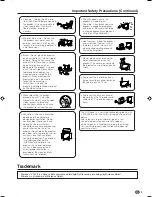
Page 4: ...entilation openings This product is not designed for built in installation do not place the product in an enclosed place such as a bookcase or rack unless proper ventilation is provided or the manufacturer s instructions are followed The LCD panel used in this product is made of glass Therefore it can break when the product is dropped or applied with impact Be careful not to be injured by broken g...

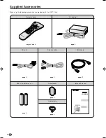
Page 5: ...provided with the LCD TV set Supplied Accessories LC 20B6H Operation manual Remote control AAA size batteries 2 AC adapter pages 5 and 9 page 5 page 6 Antenna cable page 6 RGB cable Cable holder page 8 AC cord page 27 page 6 Cable clamp page 8 ...

Page 6: ...rom batteries can cause a rash If chemical leakage is found wipe it off with a cloth The batteries supplied with the LCD TV set may have a shorter operating time due to storage conditions If the remote control is not to be used for an extended period of time remove the batteries from the remote control Preparation Engaging the lower claw with the remote control close the cover Using Remote Control...

Page 7: ...the supplied accessories No sound is heard from the main unit speakers when a headphone mini plug is connected into the HEADPHONE jack On screen display Headphones Adjust the sound volume using VOL Using the AC adapter Although the AC adapter may become warm during use this is not a malfunction Do not wrap or cover the AC adapter with a blanket or similar covering This can cause a malfunction or a...

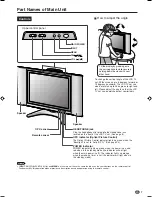
Page 8: ...n when the Backlight is set to Auto OPC See page 23 POWER indicator POWER indicator lights up green when the power is on and red when in the standby mode the indicator will not light when the main power is off The indicator lights up orange when the wake up timer is set the indicator will light when in the standby mode To change the vertical angle of the LCD TV set tilt the screen up to 5 degrees ...

Page 9: ... cables connected to each terminal through the holes and close the left and right terminal covers Push the cables into the grooves of the support cover Insert the cable holder supplied from above the support cover and fix the cables Terminal cover Cable holder Terminal cover Support cover Cable clamp When the cables cannot be pushed into the grooves of the support cover use the cable clamp supplie...

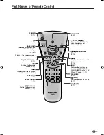
Page 10: ...urns to normal screen P 14 VOL P 11 Flashback Returns to the previous channel P 11 MPX Switches to the audio mode P 25 Right Left Selection P 14 RETURN Returns to the previous screen Upwards Downwards Selection P 14 POWER P 10 LANGUAGE P 22 Status Display Turns on the status display when the menu is not displayed P 24 BACKLIGHT Selects the brightness and OPC of the display P 23 TIMER Displays the ...

Page 11: ... the COMPONENT1 terminal COMPONENT2 Select this mode when viewing the signals from the video equipment connected to the COMPONENT2 terminal In this case set Terminal select to COMPONENT2 See page 21 AV1 Select this mode when viewing the signals from the video equipment connected to the AV1 terminal In this case set Terminal select to AV1 See page 21 The S VIDEO terminal is additionally provided fo...

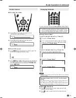
Page 12: ...se the selection will not be made Changing channels with CH on the remote control Press CH and the channels change in the order shown below 1 2 3 98 99 0 1 2 3 Press CH and the channels change in the order shown below 3 2 1 0 99 98 3 2 1 Using A A A A A Flashback Press A A A A A to switch the currently tuned channel to the previously tuned channel Press A A A A A again to switch back to the curren...

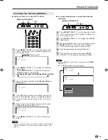
Page 13: ... the normal screen Presetting the Channels AUTO Automatically tunes in and presets receivable TV stations Make sure the antenna cable is properly connected Upper control panel 2 1 Press MENU PRESET 1 on the upper part of the LCD TV set for more than 2 seconds to display the AUTO mode screen Auto B G VHF 1 48 25MHz Press VOL PRESET 2 on the upper part of the LCD TV set All the TV stations in your a...

Page 14: ... to the normal screen NOTE System may not have been set correctly if noise can be heard or if there is no sound In such case adjust Sound system See page 14 Presetting the Channels MANUAL In a weak reception area or under bad reception conditions Upper control panel 4 1 2 3 5 Press MENU PRESET 1 on the upper part of the LCD TV set for more than 2 seconds to display the AUTO mode screen Press MENU ...

Page 15: ...ect the desired adjustment item M e n u M e n u S e t u p C H s e t u p A d j u s t s e t t i n g P o s i t i o n C H 1 C o l o u r s y s t e m S E C A M S o u n d s y s t e m B G S k i p O f f F i n e 8 7 1 1 5 M H z N I C A M O n A 2 O n Each time you press the setting for individual items changes as shown in the table below Press MENU to exit NOTE Switching Colour system Set the system to Auto ...

Page 16: ... r p n e s s C o l o u r s y s t e m A d v a n c e d R e s e t 0 0 0 0 0 Picture Sound Setup Features Menu setting screens For details on setting each menu item refer to the page number indicated below NOTE The illustrations and on screen displays in this manual are for explanation purposes and may vary slightly from the actual appearance Depending on the setting condition such as an input mode it...

Page 17: ...press OK 3 Basic Adjustment Settings 5 4 Selected item Contrast Brightness Colour Tint Sharpness d d d d d button For more contrast For more brightness For more colour intensity Skin tones become greenish For more sharpness c c c c c button For less contrast For less brightness For less colour intensity Skin tones become purplish For less sharpness Colour System Only AV1 or AV2 Mode Set the system...

Page 18: ...the Advanced menu and press OK 2 Press to select Yes and press OK 3 2 4 Selected item User High Middle Low Description Can be set your desired colour White with Bluish tone White with Reddish tone 5 6 Selected item Red Green Blue Press Press Weaker red Stronger red Weaker green Stronger green Weaker blue Stronger blue I P Setup Adjusting the image and input signal can give you a more beautiful pic...

Page 19: ... u r t e m p R e d G r e e n B l u e I P S e t u p D N R F i l m m o d e Q u i c k s h o o t R e s e t Press to select On and press OK M e n u M e n u P i c t u r e A d v a n c e d Q u i c k s h o o t S e l e c t e d d e s i r e d i t e m O n O f f Press MENU to exit NOTE Quick shoot may cause image noise If this occurs set the function to Off Quick shoot cannot be set when the PC mode is selected...

Page 20: ...d moves it to the foreground Voices are moved to closer to listener while other sounds are moved to the back Improves voices that are hard to understand but leaves clear voices undisturbed Perform steps 1 and 2 in Sound Adjustments to display the Sound Menu screen Press to select Advanced and press OK M e n u M e n u S o u n d A d v a n c e d P i c t u r e P i c t u r e S o u n d S o u n d S e t u...

Page 21: ...et when AV2 In Out is set to Out Sound wide cannot be set when the headphone mini plug is plugged into HEADPHONE jack 1 2 3 4 3 4 5 6 2 PC Sound Select for PC Mode You can switch the sound mode while the LCD TV set is connected to the PC Make sure the PC mode is selected before making this setting Perform steps 1 to 3 in Sound Wide to display the Advanced menu screen Press to select PC sound selec...

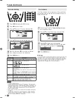
Page 22: ...lect the input mode according to the external device connected to the COMPONENT2 AV1 terminal Perform steps 1 and 2 in Display Mode to display the Setup Menu screen Press to select Terminal select and press OK M e n u M e n u S e t u p T e r m i n a l s e l e c t P i c t u r e P i c t u r e S o u n d S o u n d S e t u p S e t u p F e a t u r e s F e a t u r e s C H s e t u p C l o c k s e t u p D ...

Page 23: ...ected output volume is fixed and speaker output is available Out Line output is selected output volume is variable and speaker output is set to mute 1 2 3 4 On Screen Display Language Setting You can select English Chinese or Arabic as the on screen display language Perform steps 1 and 2 in AV2 In Out to display the Setup Menu screen Press to select Language and press OK M e n u M e n u S e t u p ...

Page 24: ... c t i o n s A u t o p o w e r o f f P o w e r m a n a g e m e n t Press to set each item in each setting screen Except Timer functions item Example Backlight setting screen M e n u M e n u F e a t u r e s B a c k l i g h t S e l e c t e d d e s i r e d i t e m A u t o O P C B r i g h t N o r m a l D a r k Press MENU to exit 1 Backlight setting can be switched in one touch using the remote control...

Page 25: ...ot be activated if the main power is turned off with MAIN POWER on the LCD TV set After the TV has been turned on by Wake up timer Sleep timer is automatically set to 120min for safety reason You can check the time set in Wake up timer by pressing Status Display When the time set for the Wake up timer is reached when the power is on the LCD TV set changes to the set channel The sound volume does n...

Page 26: ...ed individually for each channel number When stereo sound is received When monaural sound is received NICAM Broadcast Selection When main sound is selected When sub sound is selected When monaural sound is selected If the sound quality is poor due to a weak signal or other problems during NICAM broadcast reception set the Off position of the NICAM to change the TV sound to monaural Press MENU to d...

Page 27: ...due to a weak signal or other problems during A2 stereo broadcast reception set the Off position of the A2 to change the TV sound to monaural Press MENU to display the MENU screen Press to select Setup Press to select CH setup and press OK M e n u M e n u S e t u p C H s e t u p P i c t u r e S o u n d S e t u p F e a t u r e s C H s e t u p C l o c k s e t u p D i s p l a y m o d e T e r m i n a ...

Page 28: ...ames for 15 pin mini D sub connecter 15 14 13 12 9 11 10 8 7 6 5 4 3 2 1 Pin No Signal name Pin No Signal name Pin No Signal name 1 R 6 GND Ground q Not connected 2 G 7 GND Ground w SDA 3 B 8 GND Ground e HD 4 Not connected 9 Ⳮ5V r VD 5 CSYNC 0 GND Ground t SCL NOTE Pin No 5 on the LCD TV set is not used for inputting the signal Pin No 9 is not connected with the supplied RGB cable Displaying an I...

Page 29: ...l e c t e d d e s i r e d i t e m 1 2 4 7 6 8 6 4 4 8 0 0 0 Press MENU to exit Fine Sync Adjustments for PC Mode Adjust the PC image using the Fine sync menu Perform steps 1 to 3 in Input Signal for PC Mode to display the PC setup screen Press to select Fine sync and press OK M e n u M e n u S e t u p P C s e t u p F i n e s y n c I n p u t s i g n a l F i n e s y n c Press to select the specific ...

Page 30: ...using the PC and the signal inputs again the LCD TV set stays off The LCD TV set turns on again by pressing MAIN POWER on the LCD TV set or POWER on the remote control See page 10 Off is factory preset value PC Compatibility Chart NOTE The numerical values of resolutions and frequencies mentioned above are standard They may differ from the values when actually displayed Horizontal Frequency kHz 31...

Page 31: ... When you connect external devices to both terminals and if you select AV1 you can only view pictures from the S VIDEO terminal To view the picture from the VIDEO terminal do not connect any external devices to the S VIDEO terminal For more information about external device connections see the manuals of your external devices To PC IN terminal PC Example DVD Player etc Digital TV tuner To COMPONEN...

Page 32: ...l audio source is connected to only one of the AUDIO input terminals sound will be heard not from both speakers but from only one speaker PC VCR DVD Player DVD Player Camcorder VCR When connecting this type of external device select COMPONENT2 on the Terminal select of Setup menu Video Audio L Audio R Y PB PR Audio L Audio R Y PB PR Video Audio L Audio R S Video Audio R Audio L RGB cable supplied ...

Page 33: ...actory setting for AV2 In Out is In NOTE The AV IN2 OUT terminal has 2 output modes see page 22 When using the S VIDEO input for AV1 no video output will be made to the AV output terminal but audio output will be made for connec tion to external audio systems When using the S VIDEO input for AV1 or Y PB and PR input for COMPONENT no video output will be made to the AV output terminal but audio out...

Page 34: ...c electricity etc may cause improper operation In this case operate the unit after first turning the power of the Display or unplugging the AC cord and re plugging it in after 1 or 2 minutes Reference page Picture There is no picture or sound There is no picture There is no picture from AV1 AV IN2 There is no sound Picture is not clear Picture is too light or improp erly tinted The picture is too ...

Page 35: ...art as possible from devices that may cause possible interference The picture is not sharp The picture is doubled or tripled There are stripes on the screen or colours fade The picture moves The picture is spotted Antenna PC Problem Check item Make sure the RGB cable is properly connected Make sure the output signal of the PC and the input signal setting of the LCD TV set are matched Some software...

Page 36: ...adphone jack 3 5 mm ø jack Front OSD LANGUAGE English Chinese Arabic Power requirement DC 12 V AC 110 240 V 50 60 Hz Power Consumption 68 W 1 0 W Standby AC 220 V With AC adapter 58 W DC 12 V Weight 8 6 kg w o accessories Accessories Remote control Batteries 2 Antenna cable AC adapter RGB cable Cable clamp AC cord Cable holder Operation manual The typical period of time after which the lamp s powe...

Page 37: ...36 Unit mm 74 244 178 410 5 308 4 261 452 including rubber foot 191 673 384 212 393 59 450 including rubber foot 47 100 100 Dimensional Drawings ...

Page 38: ...LC 20B6H OPERATION MANUAL SHARP CORPORATION Printed in Japan TINS B286WJZZ 04P06 JMM Printed on 100 post consumer recycled paper ...

Reviews: