11
LC-20E1U
LC-20E1UB/UW
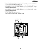
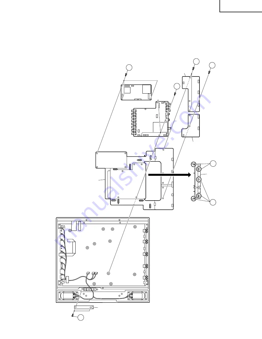
10. Remove the inverter-A PWB fixing screws (2 pcs.).
11. Remove the inverter-B PWB fixing screws (1 pc.).
12. Remove the digital PWB fixing screws (3 pcs.).
13. Remove the analog PWB fixing screws (3 pcs.) and detatch the chassis frame cover fixing
hooks.
14. Remove the R/C, LED PWB fixing screws (2 pcs.).
R/C, LED PWB
13
13
Chassis
Frame Cover
Chassis Frame
Inverter-A
PWB
Inverter-B
PWB
Digital PWB
Analog PWB
10
11
13
12
14
Summary of Contents for Aquos LC 20E1U
Page 32: ...35 34 LC 20E1U LC 20E1UB UW 12 11 10 9 8 7 6 5 4 3 2 1 A B C D E F G H OVERALL WIRING DIAGRAM ...
Page 35: ...39 38 LC 20E1U LC 20E1UB UW 12 11 10 9 8 7 6 5 4 3 2 1 A B C D E F G H Ë DIGITAL Unit 1 5 ...
Page 36: ...41 40 LC 20E1U LC 20E1UB UW 12 11 10 9 8 7 6 5 4 3 2 1 A B C D E F G H Ë DIGITAL Unit 2 5 ...
Page 37: ...43 42 LC 20E1U LC 20E1UB UW 12 11 10 9 8 7 6 5 4 3 2 1 A B C D E F G H Ë DIGITAL Unit 3 5 ...
Page 38: ...45 44 LC 20E1U LC 20E1UB UW 12 11 10 9 8 7 6 5 4 3 2 1 A B C D E F G H Ë DIGITAL Unit 4 5 ...
Page 39: ...47 46 LC 20E1U LC 20E1UB UW 12 11 10 9 8 7 6 5 4 3 2 1 A B C D E F G H Ë DIGITAL Unit 5 5 ...
Page 40: ...49 48 LC 20E1U LC 20E1UB UW 12 11 10 9 8 7 6 5 4 3 2 1 A B C D E F G H Ë ANALOG Unit 1 2 ...
Page 41: ...51 50 LC 20E1U LC 20E1UB UW 12 11 10 9 8 7 6 5 4 3 2 1 A B C D E F G H Ë ANALOG Unit 2 2 ...
Page 42: ...52 6 5 4 3 2 1 A B C D E F G H LC 20E1U LC 20E1UB UW Ë INVERTER A Unit ...
Page 43: ...53 6 5 4 3 2 1 A B C D E F G H LC 20E1U LC 20E1UB UW Ë INVERTER B Unit ...
Page 46: ...56 6 5 4 3 2 1 A B C D E F G H LC 20E1U LC 20E1UB UW DIGITAL Unit Side B ...
Page 49: ...59 6 5 4 3 2 1 A B C D E F G H LC 20E1U LC 20E1UB UW ANALOG Unit Side A ...
Page 51: ...62 6 5 4 3 2 1 A B C D E F G H LC 20E1U LC 20E1UB UW INVERTER A Unit Side A ...
Page 53: ...64 6 5 4 3 2 1 A B C D E F G H LC 20E1U LC 20E1UB UW INVERTER B Unit Side A ...


