


14
LC-20E1U
LC-20E1UB/UW
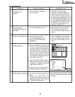
ADJUSTING PROCEDURE OF EACH SECTION
The best adjustment is made before shipping. If any position deviation is found or after part replace is performed, adjust
as follows.
1. Preparation for Adjustments
(1)Use the exclusive-use AC adapter or stable DC power supply.
AC adapter: UADP-0243CEPZ
DC power supply: 13 ± 0.5V
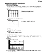
2. Special mode setting procedure
(1)After initialization of E
2
PROM the mode is changed to the adjustment mode.
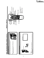
[Procedure]
Connect TP2001 and TP2002 to GND, and turn on the power.
[Description]
»
The initialization of microprocessor is as follows.
»
AV position, DAC data, G/A data, sound processor data, and video chroma data adjustment values are taken as
defaults.
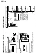
(2)Adjustment mode
[Procedure]
Short-circuit TP2001 to GND, and turn on the power.
Or short-circuit TP2002 to GND, and turn on the power.
Or holding down the [TV/VIDEO] key and [MENU] key, turn on the main power, and simultaneously press the
(inspection process) [CH
"
] key and [VOL– ] key to change the mode to the adjustment mode.
[Description]
The manual adjustment or adjustment through communication with the automatic machine is performed.
(3)Shipping setting mode
[Procedure]
Holding down the [TV/VIDEO] key and [MENU] key, turn on the main power, and simultaneously press the
(inspection process) [CH
'
] key and [VOL+] key to change the mode to the shipping setting mode.
Note: Keep it in mind to turn off the power immediately. If any key-in is accidentally made, the setting will be
canceled.
[Description]
User adjustment and other values are taken as defaults.
If TV is indicated as SETTING COMPLETE, setting has been completed.
3. Cancel of special mode
Turn off the main unit power.
Summary of Contents for Aquos LC 20E1U
Page 32: ...35 34 LC 20E1U LC 20E1UB UW 12 11 10 9 8 7 6 5 4 3 2 1 A B C D E F G H OVERALL WIRING DIAGRAM ...
Page 35: ...39 38 LC 20E1U LC 20E1UB UW 12 11 10 9 8 7 6 5 4 3 2 1 A B C D E F G H Ë DIGITAL Unit 1 5 ...
Page 36: ...41 40 LC 20E1U LC 20E1UB UW 12 11 10 9 8 7 6 5 4 3 2 1 A B C D E F G H Ë DIGITAL Unit 2 5 ...
Page 37: ...43 42 LC 20E1U LC 20E1UB UW 12 11 10 9 8 7 6 5 4 3 2 1 A B C D E F G H Ë DIGITAL Unit 3 5 ...
Page 38: ...45 44 LC 20E1U LC 20E1UB UW 12 11 10 9 8 7 6 5 4 3 2 1 A B C D E F G H Ë DIGITAL Unit 4 5 ...
Page 39: ...47 46 LC 20E1U LC 20E1UB UW 12 11 10 9 8 7 6 5 4 3 2 1 A B C D E F G H Ë DIGITAL Unit 5 5 ...
Page 40: ...49 48 LC 20E1U LC 20E1UB UW 12 11 10 9 8 7 6 5 4 3 2 1 A B C D E F G H Ë ANALOG Unit 1 2 ...
Page 41: ...51 50 LC 20E1U LC 20E1UB UW 12 11 10 9 8 7 6 5 4 3 2 1 A B C D E F G H Ë ANALOG Unit 2 2 ...
Page 42: ...52 6 5 4 3 2 1 A B C D E F G H LC 20E1U LC 20E1UB UW Ë INVERTER A Unit ...
Page 43: ...53 6 5 4 3 2 1 A B C D E F G H LC 20E1U LC 20E1UB UW Ë INVERTER B Unit ...
Page 46: ...56 6 5 4 3 2 1 A B C D E F G H LC 20E1U LC 20E1UB UW DIGITAL Unit Side B ...
Page 49: ...59 6 5 4 3 2 1 A B C D E F G H LC 20E1U LC 20E1UB UW ANALOG Unit Side A ...
Page 51: ...62 6 5 4 3 2 1 A B C D E F G H LC 20E1U LC 20E1UB UW INVERTER A Unit Side A ...
Page 53: ...64 6 5 4 3 2 1 A B C D E F G H LC 20E1U LC 20E1UB UW INVERTER B Unit Side A ...