15
LC-20E1U
LC-20E1UB/UW
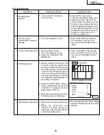
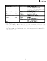
4. Adjustments
1
B+ Adjustment
(R3760)
2
Inch Size setup
(If E
2
PROM is replaced)
(IC2004)
3
Common-bias adjustment
4
TAMP adjustment
5
White balance adjustment
Adjustment
Adjusting conditions
Adjusting method
1. Connect the DC voltmeter to
pin 2 of P3702.
1. Go to the adjustment mode.
1. Receive a B/W channel.
2. Go to the adjustment mode.
3. Select the "COM BIAS" with
[MENU] key.
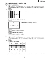
1. Receive a half color bar signal in the
TV mode so that the top left zone
should turn white 75% as shown be-
low. Other signal can be fed instead
of the half color bar signal, however,
if the point at the vertical 180th line
and horizontal 46th pixel is of white
75%. (Make the adjustment based on
the setting of this point.)
2. Adjust the “NTSC TAMP” setting on
page 2 of adjustment process mode
so that the “Y” reading on the same
page should be BB - CA.
3. Make the same setting for the PAL-
M TAMP and PAL-N TAMP data.
1. Receive the monoscope pattern sig-
nal.
2. A d j u s t t h e “ R C U T O F F ” a n d
“BCUTOFF” settings on page 2 of
adjustment process mode to achieve
an optimum white balance.
1. Adjust the "B+ Adj" value to
5.0±0.02V with R3760. Make exact
adjustment of the 5.00V level be-
cause it will be the reference for all
the other supply voltages. Be sure to
make this adjustment together with
the main PWB (digital PWB). During
the adjustment, be also careful not
to allow the voltage at pin (2) of
P3702 to go above 5.3 V.
1. Select "INCH SIZE" and adjust to
"20" with [VOL+] or [VOL-] key.
* The color of "INCH SIZE" must be
yellow.
1. Adjust "COM BIAS" to the darkest
screen with [VOL+] and [VOL-] key.
* The color of "COM BIAS" must be
yellow.
1. Do not change the “GCUTOFF” setting
because otherwise the black level may
fluctuate.
White 75% at
top left zone
Vertical 180th line and
horizontal 46th pixel
480 lines
640 pixels
Page 2 of adjustment process mode
2
|
COM BIAS
90
NTSCTAMP
20
PAL-M TAMP
20
PAL-N TAMP
20
RCUTOFF
-1
GCUTOFF
0
BCUTOFF
-1
G3
B3
R3
00
00
00
G1
B4
Y
EF
C7
C2
TAMP H
CA
TAMP L
BB
GAIBU VER0.000
“Y” data
(white 75%)
Summary of Contents for Aquos LC 20E1U
Page 32: ...35 34 LC 20E1U LC 20E1UB UW 12 11 10 9 8 7 6 5 4 3 2 1 A B C D E F G H OVERALL WIRING DIAGRAM ...
Page 35: ...39 38 LC 20E1U LC 20E1UB UW 12 11 10 9 8 7 6 5 4 3 2 1 A B C D E F G H Ë DIGITAL Unit 1 5 ...
Page 36: ...41 40 LC 20E1U LC 20E1UB UW 12 11 10 9 8 7 6 5 4 3 2 1 A B C D E F G H Ë DIGITAL Unit 2 5 ...
Page 37: ...43 42 LC 20E1U LC 20E1UB UW 12 11 10 9 8 7 6 5 4 3 2 1 A B C D E F G H Ë DIGITAL Unit 3 5 ...
Page 38: ...45 44 LC 20E1U LC 20E1UB UW 12 11 10 9 8 7 6 5 4 3 2 1 A B C D E F G H Ë DIGITAL Unit 4 5 ...
Page 39: ...47 46 LC 20E1U LC 20E1UB UW 12 11 10 9 8 7 6 5 4 3 2 1 A B C D E F G H Ë DIGITAL Unit 5 5 ...
Page 40: ...49 48 LC 20E1U LC 20E1UB UW 12 11 10 9 8 7 6 5 4 3 2 1 A B C D E F G H Ë ANALOG Unit 1 2 ...
Page 41: ...51 50 LC 20E1U LC 20E1UB UW 12 11 10 9 8 7 6 5 4 3 2 1 A B C D E F G H Ë ANALOG Unit 2 2 ...
Page 42: ...52 6 5 4 3 2 1 A B C D E F G H LC 20E1U LC 20E1UB UW Ë INVERTER A Unit ...
Page 43: ...53 6 5 4 3 2 1 A B C D E F G H LC 20E1U LC 20E1UB UW Ë INVERTER B Unit ...
Page 46: ...56 6 5 4 3 2 1 A B C D E F G H LC 20E1U LC 20E1UB UW DIGITAL Unit Side B ...
Page 49: ...59 6 5 4 3 2 1 A B C D E F G H LC 20E1U LC 20E1UB UW ANALOG Unit Side A ...
Page 51: ...62 6 5 4 3 2 1 A B C D E F G H LC 20E1U LC 20E1UB UW INVERTER A Unit Side A ...
Page 53: ...64 6 5 4 3 2 1 A B C D E F G H LC 20E1U LC 20E1UB UW INVERTER B Unit Side A ...


