


23
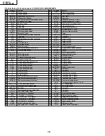
LC-20E1U
LC-20E1UB/UW
Page
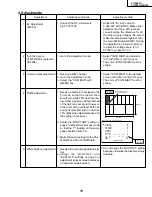
Item
Initial setting Function
Adjust/modify
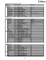
19
V255
255
Gradation power reference voltage
V255 BIAS
127
Gradation power reference voltage
V235
222
Gradation power reference voltage
V235 BIAS
127
Gradation power reference voltage
V176
130
Gradation power reference voltage
V176 BIAS
150
Gradation power reference voltage
V112
96
Gradation power reference voltage
V112 BIAS
170
Gradation power reference voltage
V64
65
Gradation power reference voltage
V64 BIAS
40
Gradation power reference voltage
V32
72
Gradation power reference voltage
V32 BIAS
100
Gradation power reference voltage
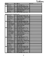
20
V21
45
Gradation power reference voltage
V21 BIAS
50
Gradation power reference voltage
V17
52
Gradation power reference voltage
V17 BIAS
145
Gradation power reference voltage
V7
27
Gradation power reference voltage
V7 BIAS
65
Gradation power reference voltage
V0
0
Gradation power reference voltage
V0 BIAS
80
Gradation power reference voltage
VGL ADJ
27
VGL bias setting
VGL COM
215
VGL COM setting
COM
179
COM amplitude setting
G/A READDATA
00 00
Controller read data setting
G/A READDATA
WAIT
Read execution
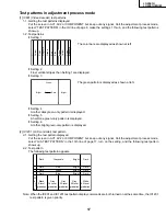
Gradation & COM settings
21
3D Y/C
2
3D ON/OFF setting
3D Y/C DATA
0
3D YC data write & read
3D Y/C DATA
WAIT
Write & read execution
LSYNC
625
Sync ID threshold level (TV)
HSYNC
655
Sync ID threshold level (TV)
AVSYNC
5000
Sync ID threshold level (external input)
VPC FP20H
DATA0000 VPC data read value
VPC FP21H
DATA0000 VPC data read value
VPC FP13H
DATA0000 VPC data read value
MSP DEMO200H
DATA0000 MSP data read value
L ERROR WAIT
15s
Lamp error detect wait time
L ERROR H TIME
1.0s
Lamp error detect time
VPC I2C 20H
24
Sync control setting (Only for Ver. 1.8)
Three-dimensional settings & sync ID settings
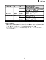
22
DENKA PORT
OFF
Power off mode setting
DENKA TESTP
00
Power off mode setting
DENKA TESTP2
30ms
Power off mode setting
FP12TIM
700
Measure against vertical baund
REMOCON CODE
000
Received remote control code display
Power off mode settings & Measure against baund setting
Summary of Contents for Aquos LC 20E1U
Page 32: ...35 34 LC 20E1U LC 20E1UB UW 12 11 10 9 8 7 6 5 4 3 2 1 A B C D E F G H OVERALL WIRING DIAGRAM ...
Page 35: ...39 38 LC 20E1U LC 20E1UB UW 12 11 10 9 8 7 6 5 4 3 2 1 A B C D E F G H Ë DIGITAL Unit 1 5 ...
Page 36: ...41 40 LC 20E1U LC 20E1UB UW 12 11 10 9 8 7 6 5 4 3 2 1 A B C D E F G H Ë DIGITAL Unit 2 5 ...
Page 37: ...43 42 LC 20E1U LC 20E1UB UW 12 11 10 9 8 7 6 5 4 3 2 1 A B C D E F G H Ë DIGITAL Unit 3 5 ...
Page 38: ...45 44 LC 20E1U LC 20E1UB UW 12 11 10 9 8 7 6 5 4 3 2 1 A B C D E F G H Ë DIGITAL Unit 4 5 ...
Page 39: ...47 46 LC 20E1U LC 20E1UB UW 12 11 10 9 8 7 6 5 4 3 2 1 A B C D E F G H Ë DIGITAL Unit 5 5 ...
Page 40: ...49 48 LC 20E1U LC 20E1UB UW 12 11 10 9 8 7 6 5 4 3 2 1 A B C D E F G H Ë ANALOG Unit 1 2 ...
Page 41: ...51 50 LC 20E1U LC 20E1UB UW 12 11 10 9 8 7 6 5 4 3 2 1 A B C D E F G H Ë ANALOG Unit 2 2 ...
Page 42: ...52 6 5 4 3 2 1 A B C D E F G H LC 20E1U LC 20E1UB UW Ë INVERTER A Unit ...
Page 43: ...53 6 5 4 3 2 1 A B C D E F G H LC 20E1U LC 20E1UB UW Ë INVERTER B Unit ...
Page 46: ...56 6 5 4 3 2 1 A B C D E F G H LC 20E1U LC 20E1UB UW DIGITAL Unit Side B ...
Page 49: ...59 6 5 4 3 2 1 A B C D E F G H LC 20E1U LC 20E1UB UW ANALOG Unit Side A ...
Page 51: ...62 6 5 4 3 2 1 A B C D E F G H LC 20E1U LC 20E1UB UW INVERTER A Unit Side A ...
Page 53: ...64 6 5 4 3 2 1 A B C D E F G H LC 20E1U LC 20E1UB UW INVERTER B Unit Side A ...