background image

In the interests of user-safety (Required by safety regulations in some countries) the set should be restored
to its original condition and only parts identical to those specified should be used.

MODEL

This document has been published to be used for
after sales service only.
The contents are subject to change without notice.

LCD COLOR TELEVISION

CONTENTS

#########

SERVICING NOTICES ON CHECKING ..............................................................................
HOW TO ORDER PARTS ....................................................................................................
IMPORTANT .........................................................................................................................
HOTEL MODE FUNCTION ..................................................................................................
ABOUT LEAD FREE SOLDER (PbF) ..................................................................................
GENERAL SPECIFICATIONS ..............................................................................................
DISASSEMBLY INSTRUCTIONS ........................................................................................
SERVICE MODE LIST ..........................................................................................................
WHEN REPLACING EEPROM (MEMORY) IC ....................................................................
SERVICING FIXTURES AND TOOLS .................................................................................
INSTALL FOR WRITING TOOLS .........................................................................................
UPDATE FOR VCTP SOFTWARE .......................................................................................
UPDATE FOR EEPROM DATA ...........................................................................................
ELECTRICAL ADJUSTMENTS ............................................................................................
TROUBLESHOOTING GUIDE .............................................................................................
BLOCK DIAGRAM ................................................................................................................
PRINTED CIRCUIT BOARDS ..............................................................................................
SCHEMATIC DIAGRAMS ....................................................................................................
WAVEFORMS ......................................................................................................................
MECHANICAL EXPLODED VIEWS .....................................................................................
REPLACEMENT PARTS LIST .............................................................................................

Page
A1-1
A1-1
A1-1
A1-2
A1-3
A2-1~A2-5
B1-1~B2-2
C-1
C-2
C-3
C-3
C-4~C-7
C-8, C-9
D-1~D-4
E-1~E-5
F-1~F-6
G-1~G-8
H-1~H-26
I-1
J-1, J-2
K1-1~K2-9

LC-20S5E-BK

SERVICE MANUAL

SHARP CORPORATION

Summary of Contents for aquos LC-20S5E-BK

Page 1: ...PORTANT HOTEL MODE FUNCTION ABOUT LEAD FREE SOLDER PbF GENERAL SPECIFICATIONS DISASSEMBLY INSTRUCTIONS SERVICE MODE LIST WHEN REPLACING EEPROM MEMORY IC SERVICING FIXTURES AND TOOLS INSTALL FOR WRITING TOOLS UPDATE FOR VCTP SOFTWARE UPDATE FOR EEPROM DATA ELECTRICAL ADJUSTMENTS TROUBLESHOOTING GUIDE BLOCK DIAGRAM PRINTED CIRCUIT BOARDS SCHEMATIC DIAGRAMS WAVEFORMS MECHANICAL EXPLODED VIEWS REPLACE...

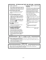
Page 2: ... the original positions or whether there are the portions which are deteriorated around the serviced places serviced or not Check the insulation between the antenna terminal or external metal and the AC cord plug blades And be sure the safety of that INSULATION CHECK PROCEDURE 1 2 3 4 Unplug the plug from the AC outlet Remove the antenna terminal on TV and turn on the TV Insulation resistance betw...

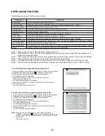
Page 3: ... Effective invalid setting of main key operation Note 4 Effective invalid setting of menu key operation of set and remote cotrol Note 4 Setting of the maximum volume value 1 50 On Screen Display Input mode start Input mode fixed Reset Display non display setting of analog menu CALL CH audio backlight and volume level Note 5 Setting of input source at power supply On During the power on effective i...

Page 4: ...ture soldering iron please be careful not to heat too long Pb free solder will tend to splash when heated too high about 1100 F 600 C All products with the printed circuit board with PbF printing must be serviced with lead free solder When soldering or unsoldering completely remove all of the solder from the pins or solder area and be sure to heat the soldering points with the lead free solder unt...

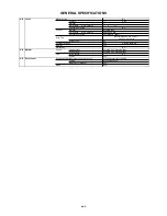
Page 5: ...nd FS 33 4 32 9 32 4 40 4 MHz FP FS 5 5 6 0 6 5 6 5 MHz Digital ATS Area Setting Germany Auto Tuning Method ALL Band Not CCIR CH Plan Preset CH Analog 99 Digital Stereo Dual TV Sound Nicam A2 Dual Tuner Sound Muting Yes G 3 Power Power Source AC 220 240V AC 50 60Hz DC Power Consumption at AC 74W at AC 230V 50Hz at DC Stand by at AC 1W Per Year kWh Year Protector Power Fuse Yes Safety Circuit Yes I...

Page 6: ...BACKLIGHT Yes Mute Yes 1 Yes 2 Yes 3 Yes 4 Yes 5 Yes 6 Yes 7 Yes 8 Yes 9 Yes 0 Yes Flashback Yes Input select Yes Volume up Yes Volume down Yes Channel up Yes Channel down Yes WIDE MODE Yes Sound Mode Yes Display information Yes SLEEP Yes Teletext Yes MENU Yes UP Yes LEFT Yes OK Channel list Yes RIGHT Yes DOWN Yes END Yes TOP BOTTOM FULL Yes REVEAL Yes HOLD Yes SUBTITLE Yes SUBPAGE Yes RED Yes GRE...

Page 7: ...lor Temperature Yes Sound Setting Tone Control Bass Treble Balance Yes Sound via No Auto Vol Yes Clear Voice Yes Sound wide Yes Lock Hotel Lock Yes Child Lock Yes PC Monitor Input Yes VGA 640x480 Yes 60Hz VGA 720x400 No WVGA 848x480 No SVGA 800x600 Yes 60Hz XGA 1024x768 No WXGA 1280x768 No WXGA 1280x720 No WXGA 1360x768 No SXGA 1280x1024 No Variable Audio Out No Freeze frame No Choke Coil No Rec S...

Page 8: ... Switch Side Sub Power Tact Yes System Select No Main Power SW No Sub Power Push No Channel Up Menu Up Yes Channel Down Menu Down Yes Volume Up Menu Yes Volume Down Menu Yes Input Select Yes Menu Yes Indicator Power No Stand by No Power Stand By Yes Green Red On Timer No OPC No Terminals Rear Video Output No Color Stream 2 No Diversity No Ext Speaker No DC Jack 12V Center No Bottom VHF UHF Antenna...

Page 9: ...e in Japan Drop Test Natural Dropping At 1 Corner 3 Edges 6 Surfaces Height cm 60 Container Stuffing 560 Sets 40 container w Pallet Yes w Wrapping No G 16 Material Cabinet Cabinet Front PC ABS 94V 0 Non Halogen Cabinet Rear PC ABS 94V 0 Non Halogen PCB Non Halogen No Eyelet Yes G 17 Environment Environmental standard requirement by buyer Green procurement of SHARP Pb free Phase3 Phase3A Measures f...

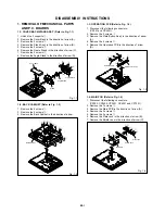
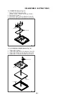
Page 10: ...arrow A Remove the 4 screws 2 Remove the Operation PCB in the direction of arrow B Fig 1 3 1 2 BACK CABINET Refer to Fig 1 2 1 2 3 Remove the 9 screws 1 Remove the 4 screws 2 Remove the Back Cabinet in the direction of arrow Fig 1 2 Fig 1 1 Cover Back Stand A 2 2 1 1 B 2 4 3 C D Angle Stand Frame Stand 3 3 4 Back Cabinet 2 1 1 1 1 1 1 11 1 2 2 2 1 4 MAIN PCB Refer to Fig 1 4 1 2 3 4 5 6 7 Disconne...

Page 11: ...in the direction of arrow A Remove the Holder PCB in the direction of arrow B 1 6 LCD COVER LCD PANEL Refer to Fig 1 6 1 2 3 4 Remove the 2 screws 1 Remove the Angle Frame in the direction of arrow A Remove the LCD Cover in the direction of arrow B Remove the LCD Panel in the direction of arrow C Fig 1 6 1 Power PCB B A 1 1 1 1 Holder PCB Front Cabinet Angle Frame 1 A B C LCD Panel LCD Cover 1 ...

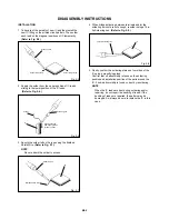
Page 12: ...t the IC leads using a blower type IC desoldering machine Refer to Fig 2 2 2 Fig 2 2 NOTE Do not rotate or move the IC back and forth until IC can move back and forth easily after desoldering the leads completely When IC starts moving back and forth easily after desoldering completely pickup the corner of the IC using tweezers and remove the IC by moving with the IC desoldering machine Refer to Fi...

Page 13: ...2 8 Thin tip Soldering Iron NOTE When the IC leads are bent during soldering and or repairing do not repair the bending of leads If the bending of leads are repaired the pattern may be damaged So always be sure to replace the IC in this case Finally confirm the soldering status on four sides of the IC using a magnifying glass Confirm that no abnormality is found on the soldering position and insta...

Page 14: ...memories are reset such as the channel setting and the POWER ON total hours POWER ON total hourson the screen Can be checked of the INITIAL DATA of MEMORY IC Refer to the WHEN REPLACING EEPROM MEMORY IC Set Key Operations Remocon Key VOL DOWN Minimum 1 2 sec Standard Time VOL DOWN Minimum 6 2 sec VOL DOWN Minimum 9 2 sec Set Condition POWER ON Display of the Adjustment MENU on the screen Refer to ...

Page 15: ...step through the ADDRESS until required ADDRESS to be changed is reached Press RIGHT LEFT button to select DATA When DATA is selected it will blink Again step through the DATA using UP DOWN button until required DATA value has been selected Pressing RIGHT LEFT button will take you back to ADDRESS for further selection if necessary Repeat steps 4 to 6 until all data has been checked When satisfied ...

Page 16: ... DISC JG203 MICON PROGRAM JIG KIT 25 4 INSTALL FOR WRITING TOOLS 1 2 Set the MICON UPDATE TOOL DISC JG204 to PC Install the LPT driver Re boot the PC Install the Setup_Visual_I2C_v3 2 3b8h exe Install the Setup_VI2C_for_VCT6wxyP_v0202 exe 3 4 5 It is necessary to install according to the PC Windows 95 98 Setup_LptDrv_v0104_9x exe Windows 2000 XP Setup_LptDrvDev_v020201_XP_2000 exe Windows NT Setup...

Page 17: ...e VCTP Writing Tools Select the LPT Preferences from File Preferences menu then input 5 to the value of Delay and press OK NOTE This step is not necessary from next time Using the MICON PROGRAM JIG KIT 25 4 JG203 connect the PC Terminal and 1 4 pin of CP802 on the Main PCB JG203 Red line 1 pin of CP802 8 CP802 JG203 Main PCB Before Update the VCTP Software it is necessary to install the WRITING TO...

Page 18: ...f Bootloader Version and check it again 9 UPDATE FOR VCTP SOFTWARE 10 When the number of the side of the check box becomes 40 you can proceed to next step If the number doesn t become 40 check the connection and try again from step 1 NOTE ...

Page 19: ...C 6 Press the Erase Flash Then press the Load Bin Flash twice Press the and select the writing Firmware 11 UPDATE FOR VCTP SOFTWARE 12 ...

Page 20: ...ishing of the writing window will close 13 UPDATE FOR VCTP SOFTWARE 14 Finish the writing unplug the AC cord and remove the MICON PROGRAM JIG KIT 25 4 JG203 Insert the AC cord again turn on the power Press both VOL DOWN button on the set and Channel button 2 on the remote control for 2 seconds Confirm that displayed version agreement with writing 15 16 17 18 ...

Page 21: ...LS refer to the INSTALL FOR WRITING TOOLS Set to the standby mode and remove the back cabinet Using the MICON PROGRAM JIG KIT 25 4 JG203 connect the PC Terminal and Pin 1 4 of CP802 on the Main PCB JG203 Red line 1 pin of CP802 Set the EU LCD MICON VER UP ROM DISC JG176 to PC Start the VCTP Writing Tools Press the NVM 1 2 CP802 JG203 Main PCB 3 4 5 ...

Page 22: ...riting will start After the finishing of the writing the window will close 8 Finish the writing unplug the AC cord and remove the MICON PROGRAM JIG KIT 25 4 JG203 Insert the AC cord again turn on the power Press both VOL DOWN button on the set and Channel button 2 on the remote control for 2 seconds Confirm that displayed version agreement with writing 9 10 11 12 ...

Page 23: ...37 38 39 40 41 42 43 FUNCTION H POSI MIN V POSI V POSI MAX V POSI MIN BAK LIGHT CENTER BAK LIGHT MAX BAK LIGHT MIN BRIGHT CENTER BRIGHT MAX BRIGHT MIN TINT CENTER CONTRAST CENTER CONTRAST MAX CONTRAST MIN CONTRAST 50 COLOR CENTER COLOR MAX COLOR MIN TEXT H POSI TEXT V POSI DAC VCOM Prepare the following measurement tools for electrical adjustments 1 Pattern Generator Fig 2 2 2 2 WHITE BALANCE 1 2 ...

Page 24: ...230 230 230 230 230 230 230 230 230 230 230 230 230 230 230 230 230 230 230 230 230 230 230 230 230 230 230 230 29 BAK LIGHT MIN 48 48 48 48 48 48 48 48 48 48 48 48 48 48 48 48 48 48 48 48 48 48 48 48 48 48 48 48 30 BRIGHT CENTER 12 12 12 12 12 12 12 12 12 12 12 12 12 12 12 12 12 12 12 12 12 12 12 12 12 12 12 12 31 BRIGHT MAX 40 40 40 40 40 40 40 40 40 40 40 40 40 40 40 40 40 40 40 40 40 40 40 40 ...

Page 25: ...ON CP7201 CP102 POWER PCB MAIN PCB AC IN CD3810 OS2201 CP2200 OPERATION PCB REMOCON PCB CD7201 D 4 CP503 CP4301 J4205 J4206 TU001 J4200 J4208 CP4302 CP3401 CP3400 CP302 CP301 CP4201 CP502 CD2200 J2200 J2201 J2202 CP2201 SPEAKER CP6705 CP6703 CP6702 CP6701 CP6700 CP501 CD3401 CD3402 CD4302 CD306 ...

Page 26: ...R ON Is F501 broken Is there voltage at pin 4 of IC501 at 18 9V Is there voltage at pin 2 of IC504 at 3 3V Change F501 Check IC501 and peripheral circuit Change AV PCB No Yes Check IC504 and peripheral circuit Or change IC504 No No Yes Yes E 1 ...

Page 27: ...TING GUIDE THE PICTURE DOES NOT APPEAR Is there signal at CP7201 Is there signal at IC7201 Change CP7201 Change IC7201 Check IC803 Or change SCALER PCB Is CD7201 connected Connected CD7201 No No No Yes Yes Yes E 2 ...

Page 28: ...BLESHOOTING GUIDE Is setting of color normal Is the color signal received Change the setting of color Receive the color signal Check IC803 and peripheral circuit THE COLOR DOES NOT APPEAR Yes No Yes No E 3 ...

Page 29: ...re signal at pins 83 and 84 of IC803 Is there color signal at pins 57 58 59 and 60 of IC801 Check IC803 and peripheral circuit Check IC801 and peripheral circuit Change MAIN PCB Yes No Yes No ON SCREEN DISPLAY DOES NOT APPEAR E 4 ...

Page 30: ...TROUBLESHOOTING GUIDE THE SCREEN HAS A VERTICAL LINE OR A HORIZONTAL LINE Change V2301 No Yes Change IC803 Is there a normal waveform at pins 118 119 and122 of IC803 E 5 ...

Page 31: ...C801 KEYB 160 AT24C256BN 10SU 1 8 KEYC 162 SDA AV3_CVBS_IN 189 AV3_Y_IN 184 S_SW 101 X801 AV3_C_IN 183 20 25MHz AV3_AUDIO_L 12 AV3_AUDIO_R 11 AV3_AUDIO_L 10 AV3_AUDIO_R 9 SP_AUDIO_OUT_L 28 SP_AUDIO_OUT_R 27 RS232C_RX 92 RS232C_TX 91 124 169 185 8 AT1 8V REG IC3401 BD7820FP SYSTEM RESET IC802 PST3229NR AT1 8V REG IC3402 BD7820FP SCALER RSDS DAC MICOM REGULATOR BLOCK DIAGRAM AT3 3V DAC IC7201 BD8139...

Page 32: ...O OUT JACK L_OUT 3 J4200 AV2 13P2 07H L_IN 6 2 21 C IN 15 3 MONITOR OUT 19 MONITOR OUT VIDEO IN 20 P CON5V PC CP4302 D229FD015G107BY SP_AUDIO_OUT_L VGA R 1 SP_AUDIO_OUT_R HSYNC 13 SOUND B VGA G 2 PC_AUDIO_L VSYNC 14 PC_AUDIO_R VGA B 3 RS 232C RECEIVER AV3_CVBS_IN IC102 ISL83220ECVZ T AV3_AUDIO_R AV3_AUDIO_L RS 232C CP102 8 9 AV3_Y_IN MD24 95V EC AV3_C_IN 2 13 11 SC2_A_OUT_L 3 SC2_A_OUT_R TUNER SOU...

Page 33: ...D508 1 3 2 4 D505 6 1 3 2 D515 D520 3 1 IC3403 KIA431A AT 1 4 IC501 STR W6765 4 1 IC502 PS2561AL1 1 V W 3 2 3 1 IC503 KIA431A AT 1 2 IC504 LA5779 13 15 Tuner_ 32V INV_GND LCD_ 32V SOUND_GND AT 3 3V P CON 6V D506 D507 2 4 P CON 9V IC3404 BAOOBCOWRP AT 14V Q502 KRA102SRTK Q504 KRC102SRTK UNREG 6V F 5 F 6 ...

Page 34: ...82 C842 C840 R879 R876 C839 R875 R874 C838 C837 R873 R872 C835 C834 C833 L7202 C832 C830 R868 R867 R866 R865 R864 C827 C826 C825 R861 C824 R860 C822 R858 R857 R856 C819 R855 R852 R851 R850 X801 R849 R844 C808 R843 R842 R841 R840 C803 R839 R838 R837 R836 R835 R834 R833 R831 R830 R829 R828 R827 R826 R825 R824 R823 R822 R821 R820 R819 R818 R816 R815 R812 R811 R810 R807 R802 B813 B801 C828 R7239 R7238...

Page 35: ... R4217 D4206 Q4213 R4272 Q4214 R4276 R4275 R4215 D4205 Q4202 R4201 R4221 R4245 Q4203 C4209 R4255 R4263 Q4212 R4262 R4266 R4269 C4222 C4237 R4281 R4282 Q4215 R4280 R4278 R4279 C4235 B4205 B4206 B809 B808 B807 B806 B805 B804 B803 B802 C899 C891 C889 D829 C888 C887 D827 D826 C886 D825 D824 D820 D821 D822 C881 D823 D819 D818 D817 C875 C871 C870 C869 C868 C866 C865 C863 D800 C852 C855 C853 C854 C856 C8...

Page 36: ... R4241 R4224 R4217 D4206 Q4213 R4272 Q4214 R4276 R4275 R4215 D4205 Q4202 R4201 R4221 R4245 Q4203 C4209 R4255 R4263 Q4212 R4262 R4266 R4269 C4222 C4237 R4281 R4282 Q4215 R4280 R4278 R4279 C4235 B4205 B4206 B809 B808 B807 B806 B805 B804 B803 B802 C899 C891 C889 D829 C888 C887 D827 D826 C886 D825 D824 D820 D821 D822 C881 D823 D819 D818 D817 C875 C871 C870 C869 C868 C866 C865 C863 D800 C852 C855 C853 ...

Page 37: ...03 W034 W035 W036 CP2200 R2205 W037 J2202 J2200 W038 J2201 W040 W078 W041 W042 W043 W044 W045 W046 W047 R511 W048 L512 L509 L505 C515 W049 W051 W813 W052 W053 W054 W809 W055 W056 W057 W058 W059 W060 W061 W062 W811 D511 W063 T501 W064 W065 W066 W067 D521 W068 W069 W070 W071 W072 R540 R541 Q513 W073 W074 D523 R 5 4 7 R529 R537 C526 D518 C522 D514 R527 L504 C524 D536 R515 R520 D513 R521 R525 C521 D51...

Page 38: ...6705 R6712 R6713 D6702 R6709 C6729 R6708 C6741 Q6703 Q6704 C6738 R6711 R6710 R6735 C6703 C6750 R6702 Q6702 C6740 Q6701 Q6700 Q6716 R536 C2209 R2209 R2208 R2207 R2204 R2201 R2202 R2203 R2206 B2200 B2201 B2202 R530 Q505 R533 Q506 R532 R513 R576 Q511 R546 R582 R542 Q512 R522 R523 R524 C518 R518 Q503 C520 R517 R526 R519 Q501 Q502 Q504 R534 R548 R545 R531 D517 C512 C508 R509 C511 C513 C2205 R2212 C500 ...

Page 39: ...N AND PICTURE IS NORMAL WITH THE DIGITAL TESTER WHEN THE COLOR BROADCAST NOTE THE DC VOLTAGE AT EACH PART WAS MEASURED OF PRINTING AND SUBJECT TO CHANGE WITHOUT NOTICE NOTE THIS SCHEMATIC DIAGRAM IS THE LATEST AT THE TIME C4209 22P CH C4210 270P CH C4230 100P CH C4245 100P CH C4233 100P CH C4215 0 0047 B C4212 0 0022 B C4202 0 0022 B C4207 0 0047 B C4225 0 01 B C4213 0 0047 B C4211 0 0022 B C4201 ...

Page 40: ...K 1 4W R3420 22K 1 4W R3424 100K R3437 22K 1 4W R3423 22K 1 4W R3434 100 R3433 1K 1 WAS RECEIVED IN GOOD CONDITION AND PICTURE IS NORMAL WITH THE DIGITAL TESTER WHEN THE COLOR BROADCAST NOTE THE DC VOLTAGE AT EACH PART WAS MEASURED OF PRINTING AND SUBJECT TO CHANGE WITHOUT NOTICE NOTE THIS SCHEMATIC DIAGRAM IS THE LATEST AT THE TIME C3427 1 B C3428 1 B C3425 0 1 B C3422 0 1 B C3439 0 0033 B C3433 ...

Page 41: ... UDZS5 6B Q4209 KTC3875S_Y_RTK MUTE Q4207 KTC3875S_Y_RTK MUTE L4227 22uHNLV25 L4208 22uHNLV25 R4244 390 R4243 390 R4232 10K R4229 10K R4287 100 R302 150 1 2W R304 150 1 2W R4236_1 390 R4237 5 6K R4207 1K R4212 1K R4203 75 R4204 75 R4205 100 R4235_1 390 R4238 5 6K WAS RECEIVED IN GOOD CONDITION AND PICTURE IS NORMAL WITH THE DIGITAL TESTER WHEN THE COLOR BROADCAST NOTE THE DC VOLTAGE AT EACH PART W...

Page 42: ...00 R002 100 R003 100 R010 120 R001 560K WAS RECEIVED IN GOOD CONDITION AND PICTURE IS NORMAL WITH THE DIGITAL TESTER WHEN THE COLOR BROADCAST NOTE THE DC VOLTAGE AT EACH PART WAS MEASURED OF PRINTING AND SUBJECT TO CHANGE WITHOUT NOTICE NOTE THIS SCHEMATIC DIAGRAM IS THE LATEST AT THE TIME C012 47P CH C013 47P CH C005 220P CH C007 47P CH C008 47P CH C006 0 1 B C011 100P CH C002 470 6 3V YK C003 47...

Page 43: ...UTE SW R317 2 2K R315 2 2K R307 33K R300 1K R4327 3301 4W R4335 330 1 4W R305 33K R310 6 8K R306 47K1 4W R318 1 8K 1 4W R319 2 2K 1 4W R320 1 8K 1 4W R321 2 2K 1 4W R314 1K R316 1K R312 820 WAS RECEIVED IN GOOD CONDITION AND PICTURE IS NORMAL WITH THE DIGITAL TESTER WHEN THE COLOR BROADCAST NOTE THE DC VOLTAGE AT EACH PART WAS MEASURED OF PRINTING AND SUBJECT TO CHANGE WITHOUT NOTICE NOTE THIS SCH...

Page 44: ... LIGHT_CONTROL1 S_SW KEY C STANDBY_LED RSDS_RESET GND GND S_3 3FL S_3 3DAC LIGHT_CONTROL2 S_3 3IO1 S_3 3IO2 S_1 8FE S_1 8FE RS232C_RX S_3 3FE RS232C_TX GND REMOCON HSYNC S_1 8DIG SCART2 VGA B SCART1 VGA G S_3 3FL VGA R AT 3 3V SCART1_Y_IN GND GND SCART1_B_IN SDA I2C_OFF SCL SCART1_G_IN SDA SCART1_R_IN SCL AV3_C_IN GND AV3_Y_IN GND AT 3 3V PANEL_ON H1 AT 3 3V PANEL_ON H2 SYS_POWER_H LIGHT_CONTROL1 ...

Page 45: ...25 W827 W809 UD GCK GSP1 GSP2 POWER P CON 3 3V P CON 3 3V VH63 VH55 DCLK1 DR9 DR8 VH31 DR7 DR6 VH7 VH0 DR5 DHS R3 DR4 DVS R3 DG9 DEN R2 LBR_S DG8 REV R2 DG7 VH55 LS SPIO DG6 R1 SPOI DG5 R1 DG4 DR4 VH7 B1 B1 DB9 DR5 G3 B2 DB8 VH0 B2 G3 B3 DB7 B3 DR6 G2 DB6 VL63 CK DB5 DR7 G2 CK DB4 VL55 DR8 G1 DCLK1 DR9 G1 DEN G1 G1 DVS G2 DHS G2 CK VL7 G3 G3 CK RSDS_RESET RSDS_HSCAN DG4 B3 RSDS_VSCAN R1 DG5 B3 SDA...

Page 46: ...2 100 R103 100 R104 10K R4316 10K R4322 10K WAS RECEIVED IN GOOD CONDITION AND PICTURE IS NORMAL WITH THE DIGITAL TESTER WHEN THE COLOR BROADCAST NOTE THE DC VOLTAGE AT EACH PART WAS MEASURED OF PRINTING AND SUBJECT TO CHANGE WITHOUT NOTICE NOTE THIS SCHEMATIC DIAGRAM IS THE LATEST AT THE TIME C4264 0 0056 B C4265 0 0056 B C103 0 1 B C124 0 1 B C128 0 1 B C127 0 1 B C126 0 1 B C125 0 1 B C4301 0 1...

Page 47: ... GOOD CONDITION AND PICTURE IS NORMAL WITH THE DIGITAL TESTER WHEN THE COLOR BROADCAST NOTE THE DC VOLTAGE AT EACH PART WAS MEASURED OF PRINTING AND SUBJECT TO CHANGE WITHOUT NOTICE NOTE THIS SCHEMATIC DIAGRAM IS THE LATEST AT THE TIME C3400 1 B C3404 0 1 B C3402 1 B C3410 0 1 B C3408 1 B C3406 1 B C3416 0 1 B C3412 1 B C3414 1 B C3239 1 B C3237 1 B C3403 100 10V YK C3401 100 10V YK C3409 100 10V ...

Page 48: ... 25V ZL C531 100 25V YXF C529 100 6 3V YXF C533 1000 6 3V ZL C532 1000 16V ZL C510 1 50V YXF C505 4 7 50V YXF C554 0 0022 250V KX C500 0 1 B C535 1 B C513 0 001 B C518 0 0022 B C520 0 1 B C512 470P CH C508 0 47 B C503 0 22 275V ECQUL C504 470P 2KV R C515 0 039 400V PP C509 0 22 275V ECQUL C506 0 1 275V ECQUL C511 0 01 B C507 0 027 100V MMTS OF PRINTING AND SUBJECT TO CHANGE WITHOUT NOTICE NOTE THI...

Page 49: ...08 0 1 B C6729 1 B C6738 1 B C6739 1 B C6740 0 033 B C6703 0 1 B C6750 0 1 B C6741 0 033 B C6727 0 1 B C6754 0 1 B C6744 0 033 B C6723 1 B C6722 1 B C6720 0 1 B C6753 0 1 B C6743 0 033 B C6715 0 1 B C6752 0 1 B C6742 0 033 B OF PRINTING AND SUBJECT TO CHANGE WITHOUT NOTICE NOTE THIS SCHEMATIC DIAGRAM IS THE LATEST AT THE TIME WAS RECEIVED IN GOOD CONDITION AND PICTURE IS NORMAL WITH THE DIGITAL TE...

Page 50: ...FOR SAFETY USE ONES ARE B2202 HCB1608KF 181T20 B2201 HCB1608KF 181T20 B2200 HCB1608KF 181T20 B2204 MMZ1608R102CT B2205 MMZ1608R102CT B2203 MMZ1608R102CT W821 C2207 100 6 3V KA C2211 0 0022 B C2210 0 0022 B C2205 270P CH C2209 0 01 B OF PRINTING AND SUBJECT TO CHANGE WITHOUT NOTICE NOTE THIS SCHEMATIC DIAGRAM IS THE LATEST AT THE TIME WAS RECEIVED IN GOOD CONDITION AND PICTURE IS NORMAL WITH THE DI...

Page 51: ... J4206 1 10 11 12 13 14 15 16 17 18 19 2 20 21 3 4 5 6 7 8 9 H 26 H 25 INTERCONNECTION DIAGRAM CEF280 PCB270 OPERATION PCB 8 OHM 5W CD2200 CD306 CP502 CD3402 CD3401 CD4302 CEF281 PCBDA0 REMOCON PCB HV HV HV HV HV HV HV HV HV HV STANDBY LED AT 5V POWER ON LED REMOCON IN GND GND POWER ON LED STANDBY LED AT 5V REMOCON IN GND GND CEF279 PCB240 POWER PCB CMF102 PCBF40 MAIN PCB GND GND AT 3 3V EEPROM_SD...

Page 52: ...V 3 2ms 10 50μs 500mV 2 0V AV JACK SWITCH 4 2ms 11 10μs 2 0V 2 0V 5 2ms 12 10ns 2 0V 500mV TUNER RSDS 6 10μs 13 20ns 5 0V 500mV SOUND AMP 7 2 0ms 500mV The following waveforms were measured at the point of the corresponding balloon number in the schematic diagram NOTE I 1 ...

Page 53: ...105 PCB240 POWER PCB ASS Y 212 111 110 113 114 101F 101F 101C 101D 101F 101G 101B 101A 101E 101 206 206 206 206 106A 106B 106C 106C 106C 106 204 PCBDA0 REMOCON PCB ASS Y 109 212 212 212 212 212 107 108 211 210 210 212 PCBF40 MAIN PCB ASS Y 209 112 209 208 208 208 208 209 205 102C 102B 203 203 210 210 102A 102D 204 102 102E 102E 102I 203 210 203 210 203 203 115 102J 102F 102G 102H 102H 102G ...

Page 54: ...01 SMALL BAG BAND TIE POLYBAG INSTRUCTION RED CAUTION INSTRUCTION BOOK E G F I H S INSTRUCTION BOOK GR PR SW FI D N INSTRUCTION BOOK PL HU CZ SVK UKR INFORMATION SHEET INSTRUCTION BOOK KIT PACKAGE TOP PACKAGE TOP PACKAGE BOTTOM PACKAGE BOTTOM GIFT BOX PACKING CASE LABEL ...

Page 55: ...EAKER R 106C 9JD800WR00084 DAMPER SPEAKER 107 9JD752WSA0647 SHIELD JACK 108 9JD761WPA0468 PLATE JACK 109 9JD761WPA0469 HOLDER PCB 110 9JD761WSA0461 COVER LCD 111 9JD761WSA0473 ANGLE FRAME 112 9JD8965TS4025 CUSHION 65TS5 4 5x4x25 113 9JD899RFC21V0 HOLDER CORD 114 9JD800WQ0A062 FELT SHEET 115 9JD702WPA1290 COVER CONNECTOR 201 9JD8117540C0S SCREW TAPPING B0 TRUSS 4x30 202 9JD8117540A0U SCREW TAPPING ...

Page 56: ...ZENER UDZS5 6B TE 17 D807 9JDDE7RB5R62B DIODE ZENER UDZS5 6B TE 17 D808 9JDDE7RB5R62B DIODE ZENER UDZS5 6B TE 17 D809 9JDDE7RB5R62B DIODE ZENER UDZS5 6B TE 17 D810 9JDDE7RB5R62B DIODE ZENER UDZS5 6B TE 17 D811 9JDDE7RB5R62B DIODE ZENER UDZS5 6B TE 17 D812 9JDDE7RB5R62B DIODE ZENER UDZS5 6B TE 17 D813 9JDDE7RB5R62B DIODE ZENER UDZS5 6B TE 17 D814 9JDDE7RB5R62B DIODE ZENER UDZS5 6B TE 17 D815 9JDDE7...

Page 57: ...F078200 IC BD7820FP E2 IC3403 9JDI1KJ9A431A IC KIA431A AT IC3404 9JDI07F0C0WF0 IC BA00BC0WFP E2 IC7200 9JDI1SF023800 IC KE454U2380TFP IC7201 9JDI07J9139A0 IC BD8139AEFV TRANSISTORS Q001 9JDT2AA5132E0 FET KTK5132E RTK P Q002 9JDT2AA5132E0 FET KTK5132E RTK P Q300 9JDTPAAB05001 COMPOUND TRANSISTOR KRA102SRTK Q301 9JDTCAA3875SY TRANSISTOR SILICON KTC3875S_Y_RTK Q302 9JDTCAA3875SY TRANSISTOR SILICON KT...

Page 58: ...24HC51816 CORE BEADS HCB1608KF 181T20 B802 9JD024HC51816 CORE BEADS HCB1608KF 181T20 B803 9JD024HC51816 CORE BEADS HCB1608KF 181T20 B804 9JD024HC51816 CORE BEADS HCB1608KF 181T20 B805 9JD024HC51816 CORE BEADS HCB1608KF 181T20 B806 9JD024HC51816 CORE BEADS HCB1608KF 181T20 B807 9JD024HC51816 CORE BEADS HCB1608KF 181T20 B808 9JD024HC51816 CORE BEADS HCB1608KF 181T20 B809 9JD024HC51816 CORE BEADS HCB...

Page 59: ...6220J COIL 22 UH L4208 9JD0216SD220J COIL 22 UH L4211 9JD021LA6220J COIL 22 UH L4212 9JD021LA6220J COIL 22 UH L4214 9JD021LA6220J COIL 22 UH L4217 9JD021LA6220J COIL 22 UH L4227 9JD0216SD220J COIL 22 UH L7201 9JD0216S8470K COIL 47 UH L7202 9JD0216SD2R2J COIL 2 2 UH JACKS CP102 9JD063W100053 JACK MD24 95V EC J4200 9JD060K411041 RCA JACK AV2 13P2 07H J4205 9JD063Y100070 SOCKET 21PIN RGB 16C J4206 9J...

Page 60: ...ECQUL C509 9JDP2122B224M CMP 0 22 UF 275V ECQUL C514 9JDE77CHH181M CE 180 UF 400V C515 9JDP332E4393J CPP 0 039 UF 400V C522 9JDE8E2U5220D CE 22 UF 50V C523 9JDE7EYF3182M CE 1800 UF 25V C524 9JDE7EYF2102M CE 1000 UF 16V C525 9JDE8E2U5470D CE 47 UF 50V C526 9JDE8E2U5220D CE 22 UF 50V C527 9JDE7EYF3182M CE 1800 UF 25V C532 9JDE7EYF2102M CE 1000 UF 16V C554 9JDCD39E0MH3M CC 0 0022UF 250V C6700 9JDP4J7...

Page 61: ... FAST RECOVERY DAN202KT146 ICS IC501 9JDI2BT067650 IC STR W6765 IC502 9JD000220002W PHOTO COUPLER PS2561AL1 1 V W IC503 9JDI1KJ9A431A IC KIA431A AT IC504 9JDI03T057790 IC LA5779 E TRANSISTORS Q501 9JDTCAA3875SY TRANSISTOR SILICON KTC3875S_Y_RTK Q502 9JDTPAAB05001 COMPOUND TRANSISTOR KRA102SRTK Q503 9JDTNAAB05003 COMPOUND TRANSISTOR KRC102SRTK Q504 9JDTNAAB05003 COMPOUND TRANSISTOR KRC102SRTK Q505 ...

Page 62: ...11 TRANSFORMER SWITCHING ETJV27ZJ18BC JACKS CP501 9JD064Q1A0003 JACK AC CCT2302 0911 CONNECTORS CP502 9JD069S270629 CONNECTOR PCB SIDE A2001WV2 7P CP503 9JD069S2E0629 CONNECTOR PCB SIDE A2001WV2 14P CD3401 9JD06CU271301 CORD CONNECTOR CU271301 CD3402 9JD06CU2E1301 CORD CONNECTOR CU2E1301 CP6700 9JD0694W23019 CONNECTOR PCB SIDE 1747386 1 CP6701 9JD0694W23019 CONNECTOR PCB SIDE 1747386 1 CP6702 9JD0...

Page 63: ...1505R SW2203 9JD0504101T34 SWITCH TACT EVQ21505R SW2204 9JD0504101T34 SWITCH TACT EVQ21505R SW2205 9JD0504101T34 SWITCH TACT EVQ21505R SW2206 9JD0504101T34 SWITCH TACT EVQ21505R SW2207 9JD0504101T34 SWITCH TACT EVQ21505R CONNECTORS CD2200 9JD06CU272301 CORD CONNECTOR CU272301 CP2200 9JD069EVB3050 CONNECTOR PCB SIDE 00_6232_011_102_800 OTHERS J2200 9JD062R750007 PLUG DIN 417HA 01 AND OTHERS CONNECT...

Page 64: ...Z91 RESISTOR RC CARBON RESISTOR CAPACITORS CC CERAMIC CAPACITOR CE ALUMI ELECTROLYTIC CAPACITOR CP POLYESTER CAPACITOR CPP POLYPROPYLENE CAPACITOR CPL PLASTIC CAPACITOR CMP METAL POLYESTER CAPACITOR CMPL METAL PLASTIC CAPACITOR CMPP METAL POLYPROPYLENE CAPACITOR K2 9 ...

Page 65: ...nistraße 3 D 20097 Hamburg Germany January 2007 Printed in Japan No part of this publication may be reproduced stored in a retrieval system or transmitted in any form or by any means electronic mechanical photocopying recording or otherwise without prior written permission of the publisher ...

Reviews: