8
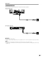
AC INPUT
DISPLAY INPUT2
DISPLAY INPUT1
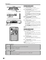
HEADPHONE
AC INPUT
DISPLAY INPUT2
DISPLAY INPUT1
Display (rear view)
AC cord
System cable
(WHITE)
Connect the plug into
the terminal and secure
it by tightning the
thumb screws.
(GRAY)
Connect the plug firmly
until the hooks on both
sides click.
Setting the system
Removing the terminal cover
2.
Connecting the system cable and the AC cord to the AVC System
L
•
TO PREVENT RISK OF ELECTRIC SHOCK, DO NOT TOUCH UN-INSULATED PARTS OF ANY CABLES WITH THE AC
CORD CONNECTED.
Preparation
DISPLAY OUTPUT-2
DISPLAY OUTPUT-1
AC INPUT
110V–240V
Press down the two
upper hooks to remove
the cover toward you.
1.
Connecting the system cable and the AC cord to the Display
DISPLAY OUTPUT-2
RS-232C
AC INPUT
DISPLAY OUTPUT-1
Y
P
B
P
R
S-VIDEO
VIDEO
R-AUDIO-L
COMPONENT
INPUT 1
INPUT 2
Y
P
B
P
R
S-VIDEO
COMPONENT
VIDEO
R-AUDIO-L
INPUT 3
HD INPUT
MONITOR OUTPUT
ANT/CABLE 75
Ω
OUT
ANT-A
ANT-B
System cable
AVC System (rear view)
AC cord
(GRAY)
(WHITE)


