background image

LC-37A37M

 i

LC37A37M

Service Manual


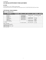
OUTLINE AND DIFFERENCES FROM BASE MODEL

OUTLINE

This model is based on the LC-32A37M and partially modified.

For the contents not covered in this Service Manual, accordingly, please refer to the LC-32A37M (SY8U6LC32A37M) Service Manual.

DIFFERENCES FROM BASE MODEL

„

LIST OF CHANGED PARTS

Ref. No.

Description

LC-32A37M

LC-37A37M

Note

PRINTED WIRING BOARD ASSEMBLIES

MAIN Unit

DUNTKF067FM05

DUNTKF067FM06

No Internal parts change

R/C, LED Unit

DUNTKF068FM01

KEYUnit

DUNTKF069FM01

POWER Unit

DUNTKF063FM03

DUNTKF064FM02

Changes

INVERTER Unit

DUNTKF071FM01

DUNTKF072FM01

Changes

GND Unit

RUNTKA550WJZZ

-

Abolish

GND Unit (Top)

-

RUNTKA552WJZZ

Addition

GND Unit (Bottom)

-

RUNTKA553WJZZ

Addition

LCD PANEL

R1LK315T3GW40W

R1LK370T3GW40W

Changes

Refer to Parts Guide.
POWER Unit (DUNTKF064FM02)
Refer to Parts Guide.
INVERTER Unit (DUNTKF072FM01)
Refer to Parts Guide.

Summary of Contents for Aquos LC-37A37M

Page 1: ...IONS 1 1 CHAPTER 2 OPERATION MANUAL 1 OPERATION MANUAL 2 1 CHAPTER 3 DIMENSIONS 1 DIMENSIONS 3 1 CHAPTER 4 REMOVING OF MAJOR PARTS 1 REMOVING OF MAJOR PARTS 4 1 CHAPTER 5 OVERALL WIRING DIAGRAM 1 OVERALL WIRING DIAGRAM 5 1 CHAPTER 6 PRINTED WIRING BOARD 1 POWER UNIT 6 1 2 INVERTER UNIT 6 4 CHAPTER 7 SCHEMATIC DIAGRAM 1 SCHEMATIC DIAGRAM 7 1 Parts Guide TopPage CONTENTS LCD COLOR TELEVISION In the ...

Page 2: ... LC 32A37M LC 37A37M Note PRINTED WIRING BOARD ASSEMBLIES MAIN Unit DUNTKF067FM05 DUNTKF067FM06 No Internal parts change R C LED Unit DUNTKF068FM01 KEYUnit DUNTKF069FM01 POWER Unit DUNTKF063FM03 DUNTKF064FM02 Changes INVERTER Unit DUNTKF071FM01 DUNTKF072FM01 Changes GND Unit RUNTKA550WJZZ Abolish GND Unit Top RUNTKA552WJZZ Addition GND Unit Bottom RUNTKA553WJZZ Addition LCD PANEL R1LK315T3GW40W R1...

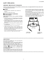
Page 3: ...s and control shafts escutcheon etc and measure the AC voltage drop across the resistor All checks must be repeated with the AC cord plug connection reversed If necessary a non polarized adaptor plug must be used only for the purpose of completing these checks Any reading of 0 74 Vrms this corresponds to 0 5 mA rms AC or more is excessive and indicates a potential shock hazard which must be correc...

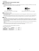
Page 4: ...l lead solder by 40 C and as it has poor solder wettability you may be apt to keep the soldering bit in contact with the PWB for extended period of time However Since the land may be peeled off or the maximum heat resistance temperature of parts may be exceeded remove the bit from the PWB as soon as you confirm the steady soldering condition Lead free solder contains more tin and the end of the so...

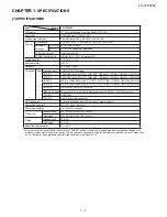
Page 5: ...NPUT 3 AUDIO in COMPONENT in 480I 576I 480P 576P 720P 50Hz 720P 60Hz 1080I 50Hz 1080I 60Hz INPUT 4 AUDIO in COMPONENT in 480I 576I 480P 576P 720P 50Hz 720P 60Hz 1080I 50Hz 1080I 60Hz INPUT 5 S VIDEO in VIDEO in AUDIO in INPUT 6 PC input 15 pin mini D sub AUDIO in common use with INPUT 1 Ø 3 5 mm jack OUTPUT AUDIO out RS 232C 9 pin D sub male connector OSD language English Simplified Chinese Tradit...

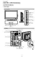
Page 6: ...ton MENU button TV VIDEO button Channel up down buttons Volume up down buttons POWER indicator OPC sensor TV Rear INPUT 5 terminals INPUT 6 PC terminals INPUT 1 HDMI terminal Antenna input terminal INPUT 2 HDMI terminal AC INPUT terminal INPUT 3 terminals OUTPUT terminals RS 232C terminal INPUT 4 terminals Remote control sensor ...

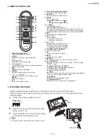
Page 7: ...lume Decrease the volume 15 CH CH TV input mode Select the channel TELETEXT mode Select the page Increase the channel number Decrease the channel number 16 TV VIDEO INPUT SOURCE Select an input source 17 PC Directly select the PC terminal 18 MENU Display the menu screen 19 RETURN MENU mode Return to the previous menu screen 20 TELETEXT Select the TELETEXT mode all TV image all TEXT image TV TEXT i...

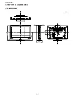
Page 8: ...LC 37A37M 3 1 LC37A37M Service Manual CHAPTER 3 DIMENSIONS 1 DIMENSIONS Unit mm 390 916 255 74 123 200 819 6 595 460 8 380 200 88 65 660 ...

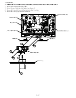
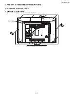
Page 9: ...37A37M 4 1 LC37A37M Service Manual CHAPTER 4 REMOVING OF MAJOR PARTS 1 REMOVING OF MAJOR PARTS 1 REMOVING OF REAR CABINET 1 Remove the 11 screws 1 3 screws 2 and detach the Rear Cabinet Rear Cabinet 1 2 1 ...

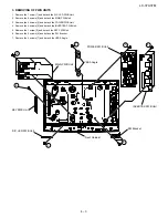
Page 10: ...d Speaker R 3 Remove the 2 screws 2 4 screws 3 and detach the Stand Cover Ass y 4 Remove the 4 screws 4 and detach the Stand Ass y Speaker R 1 3 1 3 2 4 KEY PWB Unit MAIN PWB Unit POWER PWB Unit INVERTER PWB Unit R C LED PWB Unit Speaker L Stand Ass y Stand Cover Ass y 䬌䎮䎰䬍 䬌䎳䎚䎕䎓䎕䬍 䬌䎳䎚䎕䎓䎔䬍 䬌䎦䎱䎚䎖䎓䎕䬍 䬌䎳䎛䎕䎓䎕䬍 䬌䎳䎛䎕䎓䎔䬍 䬌䎳䎛䎕䎓䎕䬍 䬌䎦䎱䎔䬍 䬌䎦䎱䎕䬍 䬌䎳䎚䎓䎓䎔䬍 䬌䎳䎧䬍 䬌䎶䎳䬍 䬌䎵䎤䬍 䬌䎶䎳䬍 䬌䎶䎳䬍 䬌䎳䎕䎖䎓䎔䬍 ...

Page 11: ...s 3 and detach the POWER PWB Unit 4 Remove the 4 screws 4 and detach the INVERTER PWB Unit 5 Remove the 1 screw 5 and detach the KEY PWB Unit 6 Remove the 2 screws 6 and detach the SW Bracket 7 Remove the 4 screws 7 and detach the VESA Angle 1 6 3 4 2 KEY PWB Unit Front Cabinet MAIN PWB Unit VESA Angle POWER PWB Unit INVERTER PWB Unit SW Bracket R C LED PWB Unit 7 5 ...

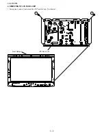
Page 12: ...LC 37A37M 4 4 4 REMOVING OF LCD PANEL UNIT 1 Remove the 4 screws 1 and detach the LCD Panel Unit from Front Cabinet 1 1 Front Cabinet LCD Panel Unit ...

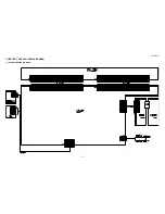
Page 13: ...LC 37A37M 5 1 LC37A37M Service Manual CHAPTER 5 OVERALL WIRING DIAGRAM 1 OVERALL WIRING DIAGRAM ...

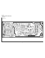
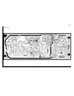
Page 14: ...LC 37A37M 6 1 LC37A37M Service Manual CHAPTER 6 PRINTED WIRING BOARD 1 POWER UNIT POWER Unit Side A 1 2 3 4 5 6 7 8 9 A B C D E F G H I J 10 11 12 13 14 15 16 17 18 19 20 21 ...

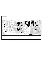
Page 15: ...LC 37A37M 6 2 POWER Unit Side B 1 2 3 4 5 6 7 8 9 A B C D E F G H I J 10 11 12 13 14 15 16 17 18 19 20 21 ...

Page 16: ... R7261 R7207 D7204 D7211 TL7203 R7271 D7210 D7223 D7225 R7257 D7203 R7269 TL7201 R7208 TL7107 C7206 D7224 C7211 C7231 TL7102 R7219 TL7202 C7203 D7216 R7136 R7135 R7123 D7105 R7103 C7102 D7103 R7111 C7106 R7112 R7117 C7105 C7101 R7124 IC7101 R7130 R7102 R7128 C7107 R7129 R7131 R7127 C7109 TL7103 R7126 FB7105 TL7108 TL7101 TL7006 TL7007 TL7008 TL7001 TL7003 TL7004 TL7002 TL7005 D7106 D7108 R7114 Q72...

Page 17: ...LC 37A37M 6 4 2 INVERTER UNIT INVERTER Unit Side A 1 2 3 4 5 6 7 8 9 A B C D E F G H I J 10 11 12 13 14 15 16 17 18 19 20 21 ...

Page 18: ... CN7908 CN7909 CN7910 C7905 CN7911 C7906 C7909 C7910 C7913 C7914 C7917 C7918 VR7700 F7700 T7902 T7907 T7910 T7903 T7906 T7911 T7900 T7904 T7908 T7901 T7905 T7909 JA101 JA102 JA103 JA104 JA105 JA106 JA107 JA108 JA109 JA301 JA302 JA303 JA110 JA304 JA111 JA305 JA112 JA306 JA113 JA307 JA114 JA308 JA309 JA310 JA311 JA312 JA313 JA314 JA315 JA316 JA317 JA901 JA902 JA903 JA904 JA905 JA906 JA907 C7800 C780...

Page 19: ...LC 37A37M 6 6 INVERTER Unit Side B 1 2 3 4 5 6 7 8 9 A B C D E F G H I J 10 11 12 13 14 15 16 17 18 19 20 21 ...

Page 20: ...736 C7952 R7737 R7738 D7930 R7739 D7931 D7932 D7933 R7930 D7934 R7931 D7935 R7932 D7936 R7933 D7937 R7740 R7934 D7938 R7741 R7935 D7939 R7742 R7936 R7743 R7937 R7744 R7938 R7745 R7939 R7746 R7747 R7748 D7940 R7749 R7940 R7941 R7942 R7943 R7750 R7944 R7751 R7945 R7752 R7946 R7753 R7947 R7754 R7948 R7755 R7949 R7756 R7757 R7950 R7951 R7952 R7953 R7954 R7955 RJ1 R7956 RJ2 R7957 R7763 RJ3 R7958 R7764 ...

Page 21: ...LC 37A37M 7 1 LC37A37M Service Manual CHAPTER 7 SCHEMATIC DIAGRAM 1 SCHEMATIC DIAGRAM 1 DESCRIPTION OF SCHEMTIC DIAGRAM ...

Page 22: ...LC 37A37M 7 2 2 POWER UNIT AND SHADED COMPONENTS SAFETY RELATED PARTS 1 2 3 4 5 6 7 8 9 A B C D E F G H I J 10 11 12 13 14 15 16 17 18 19 20 21 ...

Page 23: ...LC 37A37M 7 3 3 INVERTER UNIT AND SHADED COMPONENTS SAFETY RELATED PARTS 1 2 3 4 5 6 7 8 9 A B C D E F G H I J 10 11 12 13 14 15 16 17 18 19 20 21 ...

Page 24: ...LC 37A37M 7 4 ...
Page 25: ...shed to be used for after sales service only The contents are subject to change without notice LC 37A37M LC 37A37M LCD COLOR TELEVISION Note The reference numbers on the PWB are arranged in alphabetical order PartsGuide 1 PRINTED WIRING BOARD ASSEMBLIES 2 LCD UNIT 3 DUNTKF064FM02 POWER UNIT 4 DUNTKF072FM01 INVERTER UNIT 5 CABINET PARTS 6 LCD PANEL MODULE 7 SUPPLIED ACCESSORIES 8 PACKING PARTS NOT ...

Page 26: ...CAPACITOR C7214 VCKYCY1EB104KY AB J 0 1 25V Ceramic C7215 VCKYCY1HB104KY AA J 0 1 50V Ceramic C7217 VCKYTV1EB104KY AB J 0 1 25V Ceramic C7218 RC KZA267WJZZ AC J CAPACITOR C7219 VCKYCY1EB104KY AB J 0 1 25V Ceramic C7220 RC EZA480WJZZ AD J CAPACITOR C7221 RC EZB539WJZZ AF J CAPACITOR C7222 RC EZA480WJZZ AD J CAPACITOR C7223 RC EZB539WJZZ AF J CAPACITOR C7224 VCKYCY1HB104KY AA J 0 1 50V Ceramic C7225...

Page 27: ...7201 VS2SA1530AR 1Y AB J 2SA1530A T112 1R Q7202 RH TXA037WJZZY AE J PBLS6003D 115 Q7203 VS2SC3928AR 1Y AB J 2SC3928A T112 1R Q7205 VS2SC3928AR 1Y AB J 2SC3928A T112 1R Q7206 VS2SA1530AR 1Y AB J 2SA1530A T112 1R Q7207 VS2SC3928AR 1Y AB J 2SC3928A T112 1R Q7208 VS2SD1767Q 1Y AC J 2SD1767T100Q Q7209 VS2SC3928AR 1Y AB J 2SC3928A T112 1R Q7210 VS2SC4132Q 1Y AE J TRANSISTOR R7002 RR HZ0041CEZZY AB J RES...

Page 28: ...al Oxide R7249 VRS CY1JF472JY AA J 4 7k 1 16W Metal Oxide R7250 VRS CY1JF563FY AA J 56k 1 16W Metal Oxide R7251 VRS CY1JF563FY AA J 56k 1 16W Metal Oxide R7252 VRS TV1JD394FY AA J 390k 1 16W Metal Oxide R7253 VRS TV1JD394FY AA J 390k 1 16W Metal Oxide R7254 VRS TV1JD394FY AA J 390k 1 16W Metal Oxide R7255 VRS TV1JD394FY AA J 390k 1 16W Metal Oxide R7256 VRS TV1JD394FY AA J 390k 1 16W Metal Oxide R...

Page 29: ...C7909 RC CZA007WJZZ AC N J CAPACITOR C7910 RC CZA007WJZZ AC N J CAPACITOR C7911 VCCCCY1HH122JY AA J 1200p 50V Ceramic C7912 VCCCCY1HH122JY AA J 1200p 50V Ceramic C7913 RC CZA007WJZZ AC N J CAPACITOR C7914 RC CZA007WJZZ AC N J CAPACITOR C7915 VCCCCY1HH122JY AA J 1200p 50V Ceramic C7916 VCCCCY1HH122JY AA J 1200p 50V Ceramic C7917 RC CZA007WJZZ AC N J CAPACITOR C7918 RC CZA007WJZZ AC N J CAPACITOR C7...

Page 30: ...e R7704 VRS CY1JF221JY AA J 220 1 16W Metal Oxide R7705 VRS TQ2BD100JY AA J 10 1 8W Metal Oxide R7706 VRS TV1JD000JY AA J 0 1 16W Metal Oxide R7707 VRS TV1JD000JY AA J 0 1 16W Metal Oxide R7718 VRS CY1JF221FY AA J 220 1 16W Metal Oxide R7719 VRS CY1JF393FY AA J 39k 1 16W Metal Oxide R7720 VRS CY1JF151JY AA J 150 1 16W Metal Oxide R7721 VRS CY1JF623JY AA J 62k 1 16W Metal Oxide R7722 VRS CY1JF104JY...

Page 31: ...20 1 16W Metal Oxide R7927 VRS TV1JD821FY AA J 820 1 16W Metal Oxide R7928 VRS TV1JD821FY AA J 820 1 16W Metal Oxide R7929 VRS TV1JD821FY AA J 820 1 16W Metal Oxide R7930 VRS TV1JD821FY AA J 820 1 16W Metal Oxide R7931 VRS TV1JD821FY AA J 820 1 16W Metal Oxide R7932 VRS TV1JD332FY AA J 3 3k 1 16W Metal Oxide R7933 VRS TV1JD332FY AA J 3 3k 1 16W Metal Oxide R7934 VRS TV1JD332FY AA J 3 3k 1 16W Meta...

Page 32: ...00JY AA J 0 1 16W Metal Oxide RJ10 VRS CY1JF000JY AA J 0 1 16W Metal Oxide RJ11 VRS CY1JF000JY AA J 0 1 16W Metal Oxide RJ12 VRS CY1JF000JY AA J 0 1 16W Metal Oxide RJ14 VRS CY1JF000JY AA J 0 1 16W Metal Oxide RJ17 VRS CY1JF000JY AA J 0 1 16W Metal Oxide RJ19 VRS CY1JF000JY AA J 0 1 16W Metal Oxide RJ20 VRS CY1JF000JY AA J 0 1 16W Metal Oxide RJ21 VRS CY1JF000JY AA J 0 1 16W Metal Oxide RJ22 VRS C...

Page 33: ... 21 2 1 2 3 2 6 2 6 2 4 2 3 2 2 26 19 12 25 25 18 2 24 4 8 5 9 22 32 6 10 7 11 1 1 1 3 1 2 15 16 33 㧮 㧮 㧯 㧯 26 26 27 㧭 㧭 㧱 㧱 17 㧰 㧰 㧱 㧱 㧴 㧵 㧷 㧵 23 27 27 27 27 27 27 27 27 㧲 㧲 㧴 㧶 㧷 㧳 㧳 㧶 㧸 㧸 29 29 28 28 28 28 13 13 25 31 3 5 3 27 3 1 3 8 3 3 3 7 3 4 3 2 㨄5 2 7 2 7 2 7 2 7 ...

Page 34: ...M06 BW N V MAIN Unit 6 DUNTKF068FM01 AK N V R C LED Unit 7 DUNTKF069FM01 AG V KEY Unit 8 DUNTKF072FM01 V INVERTER Unit 9 HINDPD193WJ4A AC N J Model Label for Asia 9 HINDPD194WJ4A AC N J Model Label for Hong Kong 9 HINDPD195WJ4A AC N J Model Label for Saudi Arabia 9 HINDPD293WJ4A AC N J Model Label for Thailand 10 JBTN A812WJ4A AE N J Control Button 11 LANGKC138WJ4W AF N J SW Bracket 12 LHLDFA036WJ...

Page 35: ... AY J Diffusion Plate 19 10 CHLDZB375WJ01 AR J Lamp Holder Unit L R x2 19 11 RLMPLA048WJN1 AR J Lamp x8 19 12 QSOCFA003WJZZ AD J Lamp Socket x8 19 13 RUNTKA552WJZZ AP J GND Unit Top 19 14 RUNTKA553WJZZ AP J GND Unit Bottom 19 15 LHLDZB377WJKZ AB J Lamp Clip x8 19 16 LHLDZB378WJKZ AC J Lamp Pin x4 19 17 PMIR A230WJZZ AU J Reflector Sheet 19 18 LCHSMA550WJFW BB J BL Chassis 19 19 PCOVWA044WJKZ AQ J ...

Page 36: ... Arabia X4 LHLDWA192WJKB AE J Cable Clamp X5 CDAI A543WJ04 BB N J Stand Unit X6 TINS E055WJZZ AC N V Operation Manual English for Asia X6 TINS E111WJZZ AC N V Operation Manual Chinese Traditional for Asia X6 TINS E112WJZZ AC N V Operation Manual Chinese Simple for Asia X6 TINS E115WJZZ AC N V Operation Manual Arabic for Saudi Arabia X6 TINS E124WJZZ N V Operation Manual English for Hong Kong X6 TI...

Page 37: ...N Bottom Pad S3 SPAKPA801WJZZ Wrapping Paper S4 SPAKXC398WJZZ N Top Pad S5 SSAKA0128AJZZ Sack S6 SSAKA0005PEZZ A4 Sack S7 TLABV0182AJZZ No Card 9 SERVICE JIG USE FOR SERVICING N QCNW J413WJQZ AQ N V Harness Main Speaker N QCNW J414WJQZ AU N V Harness Main Power N QCNW J415WJQZ AT N V Harness Main LED KEY N QCNW J416WJQZ CE N V FFC Cable Main Module x2 S6 S5 X3 X1 X5 X6 S3 S2 S1 S2 S7 S4 S4 X4 X2 ...

Page 38: ...e reproduced stored in a retrieval system or transmitted in any form or by any means electronic mechanical photocopying recording or otherwise without prior written permission of the publisher SHARP CORPORATION AV Systems Group CS Promotion Center Yaita Tochigi 329 2193 Japan Mar 2009 TQ2719 S SY KY ...

Reviews: