17
LC-37HV4E
5. Adjustment
5-1 VLSBIAS/15V voltage adjustment
Shift to Item of VLS BIAS cursor up/down key, and select the value by cursor right/left key. Connect the
digital voltage meter to MAIN PWB TP4101/No.30 pin of panel gate socket CN4102, and adjust to be
15.00±0.05V by the cursor up/down key.
5-2 GRAY LEVEL/14.5V voltage adjustment
Shift to Item of GRAY LEVEL by cursor up/down key, and select the value by cursor right/left key. Connect
the digital voltage meter to MAIN PWB TP4104/near IC4105, and adjust to be 14.50±0.05V by cursor up/
down key.
This adjustment should be correctly made because this power voltage is a reference voltage of tonal
voltage.
5-3 COMBIAS adjustment
Shift to Item of COMBIAS by cursor up/down key, and select the value by cursor right/left key. If the value is
varied by cursor up/down key, the test pattern is made, so adjustment should be made so that the flicker
near the screen center becomes minimum.
5-4 Background adjustment
With AVC center connected, start the set and adjust the display background.
Sequence:
~
Display the screen for adjustment/High-side 200 gradation & Low-side 48 gradation.
~
Adjust ROFFSET, GOFFSET and BOFFSET to allow 200-gradation patterns as a standard.
Adjust the chromaticity of High pattern/screen left to be x=0.278 and y=0.283.
~
Adjust R GAMMA, G GAMMA and B GAMMA to allow 48-gradation patterns as a standard.
Adjust the chromaticity of Low pattern/screen right to be x=0.235 and y=0.230.
The above adjustment can be made in the following method:
~
Adjustment with RS-232C
~
Prepare the personal computer with
WINDOWS95/98/Me/2000/xp inputted and provided with COM port/RS-232C, together with RS-232C
cross cable.
~
Start the set with RS232C cable connected.
~
Start the terminal software. The free ware normally found on the Internet is allowed.
~
The following should be set:
Baud rate 9600
Data 8bits
Parity None
Stop 1bit
Flow control None
~
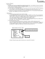
If they are set correctly, press ENTER key on the personal computer. "ERR" appears atop the terminal
software.
Summary of Contents for AQUOS LC-37HV4E
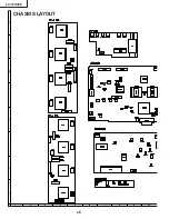
Page 26: ...26 LC 37HV4E 8 7 10 9 6 5 4 3 2 1 A B C D E F G H CHASSIS LAYOUT ...
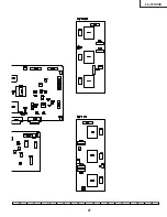
Page 27: ...27 LC 37HV4E 17 16 19 18 15 14 13 12 11 10 ...
Page 33: ...LC 37HV4E 33 6 5 4 3 2 1 A B C D E F G H Ë Ë Ë Ë Ë R C LED Unit Display ...
Page 34: ...34 LC 37HV4E 8 7 10 9 6 5 4 3 2 1 A B C D E F G H Ë MAIN Unit 1 9 Display ...
Page 35: ...35 LC 37HV4E 17 16 19 18 15 14 13 12 11 10 ...
Page 36: ...36 LC 37HV4E 8 7 10 9 6 5 4 3 2 1 A B C D E F G H Ë MAIN Unit 2 9 Display ...
Page 37: ...37 LC 37HV4E 17 16 19 18 15 14 13 12 11 10 ...
Page 38: ...38 LC 37HV4E 8 7 10 9 6 5 4 3 2 1 A B C D E F G H Ë MAIN Unit 3 9 Display ...
Page 39: ...39 LC 37HV4E 17 16 19 18 15 14 13 12 11 10 ...
Page 40: ...40 LC 37HV4E 8 7 10 9 6 5 4 3 2 1 A B C D E F G H Ë MAIN Unit 4 9 Display ...
Page 41: ...41 LC 37HV4E 17 16 19 18 15 14 13 12 11 10 ...
Page 42: ...42 LC 37HV4E 8 7 10 9 6 5 4 3 2 1 A B C D E F G H Ë MAIN Unit 5 9 Display ...
Page 43: ...43 LC 37HV4E 17 16 19 18 15 14 13 12 11 10 ...
Page 44: ...44 LC 37HV4E 8 7 10 9 6 5 4 3 2 1 A B C D E F G H Ë MAIN Unit 6 9 Display ...
Page 45: ...45 LC 37HV4E 17 16 19 18 15 14 13 12 11 10 ...
Page 46: ...46 LC 37HV4E 8 7 10 9 6 5 4 3 2 1 A B C D E F G H Ë MAIN Unit 7 9 Display ...
Page 47: ...47 LC 37HV4E 17 16 19 18 15 14 13 12 11 10 ...
Page 48: ...48 LC 37HV4E 8 7 10 9 6 5 4 3 2 1 A B C D E F G H Ë MAIN Unit 8 9 Display ...
Page 49: ...49 LC 37HV4E 17 16 19 18 15 14 13 12 11 10 ...
Page 50: ...50 LC 37HV4E 8 7 10 9 6 5 4 3 2 1 A B C D E F G H Ë MAIN Unit 9 9 Display ...
Page 51: ...51 LC 37HV4E 17 16 19 18 15 14 13 12 11 10 ...
Page 52: ...52 LC 37HV4E 8 7 10 9 6 5 4 3 2 1 A B C D E F G H Ë Ë Ë Ë Ë AUDIO Unit 1 2 Display ...
Page 53: ...53 LC 37HV4E 17 16 19 18 15 14 13 12 11 10 ...
Page 54: ...54 LC 37HV4E 8 7 10 9 6 5 4 3 2 1 A B C D E F G H Ë Ë Ë Ë Ë AUDIO Unit 2 2 Display ...
Page 55: ...55 LC 37HV4E 17 16 19 18 15 14 13 12 11 10 ...
Page 56: ...6 5 4 3 2 1 A B C D E F G H LC 37HV4E 56 Ë Ë Ë Ë Ë INVERTER 1 Unit Display ...
Page 57: ...LC 37HV4E 57 6 5 4 3 2 1 A B C D E F G H Ë INVERTER 2 Unit Display ...
Page 58: ...6 5 4 3 2 1 A B C D E F G H LC 37HV4E 58 Ë Ë Ë Ë Ë INVERTER 3 Unit Display ...
Page 59: ...LC 37HV4E 59 6 5 4 3 2 1 A B C D E F G H Ë INVERTER 4 Unit Display ...
Page 60: ...60 LC 37HV4E 8 7 10 9 6 5 4 3 2 1 A B C D E F G H Ë Ë Ë Ë Ë Power Unit Display ...
Page 61: ...61 LC 37HV4E 17 16 19 18 15 14 13 12 11 10 ...
Page 62: ...6 5 4 3 2 1 A B C D E F G H LC 37HV4E 62 Ë KEY Unit Display ...
Page 65: ...65 LC 37HV4E 17 16 19 18 15 14 13 12 11 10 ...
Page 68: ...68 LC 37HV4E 8 7 10 9 6 5 4 3 2 1 A B C D E F G H MAIN Unit Side B Ë Ë Ë Ë Ë Display ...
Page 69: ...69 LC 37HV4E 17 16 19 18 15 14 13 12 11 10 ...
Page 72: ...72 LC 37HV4E 8 7 10 9 6 5 4 3 2 1 A B C D E F G H AUDIO Unit Component Side Ë Ë Ë Ë Ë Display ...
Page 73: ...73 LC 37HV4E 17 16 19 18 15 14 13 12 11 10 ...
Page 84: ...6 5 4 3 2 1 A B C D E F G H LC 37HV4E 84 Ë Ë Ë Ë Ë Display POWER Unit Component Side ...
Page 85: ...LC 37HV4E 85 6 5 4 3 2 1 A B C D E F G H Ë Ë Ë Ë Ë Display POWER Unit Wiring Side ...


