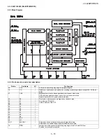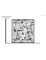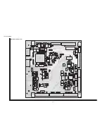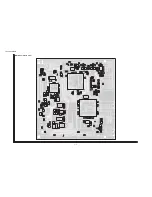
LC-42AD5E/RU/S
5 – 16
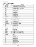
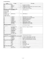
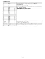
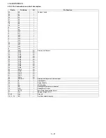
Pin No.
Pin Name
I/O
Pin Function
JTAG ball assignment
AE14
TDI
I
Boundary scan test data input (5 V tolerant)
AC14
TMS
I
Boundary scan test mode select (5 V tolerant)
AF16
TCK
I
Boundary scan test clock (5 V tolerant)
AF14
not TRST
I
Boundary scan test logic reset (5 V tolerant)
AE13
TDO
O
Boundary scan test data output (5 V tolerant)
DCU ball assignment
P1
DCUTRIGGERIN
I
External trigger input to DCU (5 V tolerant)
P3
DCUTRIGGEROUT
O
Signal to trigger external debug circuitry (5 V tolerant)
Transport stream 2 ball assignment
C23
TSIN2LBYTECLK
I/O
Transport stream bit clock (5 V tolerant)
C22
TSIN2LBYTECLKVALID
I/O
Transport stream bit clock valid edge (5 V tolerant)
B23
TSIN2LERROR
I/O
Transport stream packet error (5 V tolerant)
D19
TSIN2LPACKETCLK
I/O
Transport stream packet strobe (5 V tolerant)
B18, C18, D18, C19,
C20, D20, C21, D21
TSIN2LDATA[7:0]
I/O
Transport stream data (5 V tolerant)
(TSIN2LDATA7 is used for data input in serial mode)
Transport stream 1 ball assignment
P23
TSIN1BYTECLK
I
Transport stream bit/byte clock (5 V tolerant)
M24
TSIN1BYTECLKVALID
I
Transport stream bit/byte clock valid edge (5 V tolerant)
M26
TSIN1ERROR
I
Transport stream packet error (5 V tolerant)
N26
TSIN1PACKETCLK
I
Transport stream packet strobe (5 V tolerant)
K26, J25, H24, J24, L26,
L25, L24, M23.
TSIN1DATA[7:0]
I
Transport stream data in (5 V tolerant)
(TSIN1DATA7 is used for data input in serial mode)
EMI ball assignment
L3
not EMIRAS or not CI_IORD
O
Row address strobe for SDRAM
K1
not EMICAS or not CI_IOW
O
Column address strobe for SDRAM
J1
not EMICSA
O
Peripheral chip select A
K3
not EMICSB
O
Peripheral chip select B
K2
not EMICSC
O
Peripheral chip select C
N4
not EMICSD
O
Peripheral chip select D
J2
not EMICSE
O
Peripheral chip select E
L2
not EMICSF
O
Peripheral chip select F
L1, N3
not EMIBE[1:0]
O
External device data bus byte enable. 1 bit per byte of the data bus.
N1
not EMIOE or not CI_OE
O
External device output enable.
N2
not EMILBA or not CI_Wea
O
Flash device load burst address.
P4
EMIWAIT not TREADY
I
External memory device target ready indicator (5 V tolerant)
P2
EMIRD not WR
O
External read/write access indicator. Common to all devices.
H3, H2, G2, H4, G4, E2,
E1, E3, H1, D1, D2, C2,
G3, C1, B1, A1.
EMIDATA[15:0]
I/O
External common data bus.
D5, C5, D6, B3, A2, B2,
A3, B4, A4, C6, B5, A5,
D7, C7, B6, A6, B7, A7,
D9, C9, B9, A9, B10, C11
EMIADDR[25:2]
O
External common address bus
J3
not EMIREQGNT
O
Bus request/grant indicator
K4
not EMIACKREQ
I
Bus grant/request indicator (5 V tolerant)
L4
EMIBOOTMODE0
I
External power-up port size indicator (5 V tolerant)
G1
EMISDRAMCLK
O
SDRAM clock
J4
EMIFLASHCLK
O
Peripheral clock
Programmable I/O ball assignment
W1, U4, U2, U1, R2, R1,
T2, T1
PIO0[7:0]
I/O
Parallel input/output pin or alternative function (5 V tolerant)
AB4, Y2, AA1, Y1, W3,
U3, W2, W4
PIO1[7:0]
I/O
AF3, AD5, AE3, AE5,
AF2, Y3, AA3, AF1
PIO2[7:0]
I/O
AE18, AE4, AC16, AC12,
AE6, AC11, AC5, AE12
PIO3[7:0]
I/O
AE20, AD20, AF20,
AE19, AC17, AD18,
AD17, AF19
PIO4[7:0]
I/O
AC22, AF22, AD21,
AC21, AE21, AC18,
AC20, AF21
PIO5[7:0]
I/O
Summary of Contents for AQUOS LC-42AD5E
Page 4: ...LC 42AD5E RU S 1 1 LC 42AD5EB Service Manual CHAPTER 1 OPERATION MANUAL 1 SPECIFICATIONS ...
Page 5: ...LC 42AD5E RU S 1 2 2 OPERATION MANUAL ...
Page 6: ...LC 42AD5E RU S 1 3 ...
Page 7: ...LC 42AD5E RU S 1 4 ...
Page 8: ...LC 42AD5E RU S 1 5 ...
Page 9: ...LC 42AD5E RU S 1 6 ...
Page 10: ...LC 42AD5E RU S 1 7 3 DIMENSIONS Unit mm ...
Page 62: ...LC 42AD5E RU S 5 5 2 3 IC301 IC302 VHiTDA8931T 1Y 2 3 1 Block Diagram ...
Page 77: ...LC 42AD5E RU S 5 20 2 10 IC4203 RH iXC100WJZZQ 2 10 1 Block Diagram ...
Page 142: ...LC 42AD5E RU S 30 12 PACKING PARTS Not Replacement Item 㵘 S2 S4 S4 S4 S3 S7 S1 S4 S6 S6 S5 ...


