LC-60/70LE360X
1 – 1
CHAPTER 1.
SAFETY PRECAUTION
[1] IMPORTANT SERVICE PRECAUTION
LC
IMP OR TA NT S E R V IC E S A F E T Y P R E C A UT ION
WA R NING
1. F or continued s afety, no modification of any circuit s hould be
attempted.
2. Dis connect AC power before s ervicing.
B E F OR E R E T UR NING T HE R E C E IV E R (F ire &
S hoc k Hazard)
B efore returning the rec eiver to the us er, perform the following
s afety c hec ks :
3. Ins pect all lead dres s to make certain that leads are not pinched,
and check that hardware is not lodged between the chas s is and
other metal parts in the receiver.
4. Ins pect all protective devices s uch as non-metallic control knobs ,
ins ulation materials , cabinet backs , adjus tment and compartment
covers or s hields , is olation res is tor-capacitor networks , mechanical
ins ulators , etc.
5. To be s ure that no s hock hazard exis ts , check for leakage current in
the following manner.
•
P lug the AC cord directly into a 110-240 volt AC outlet.
•
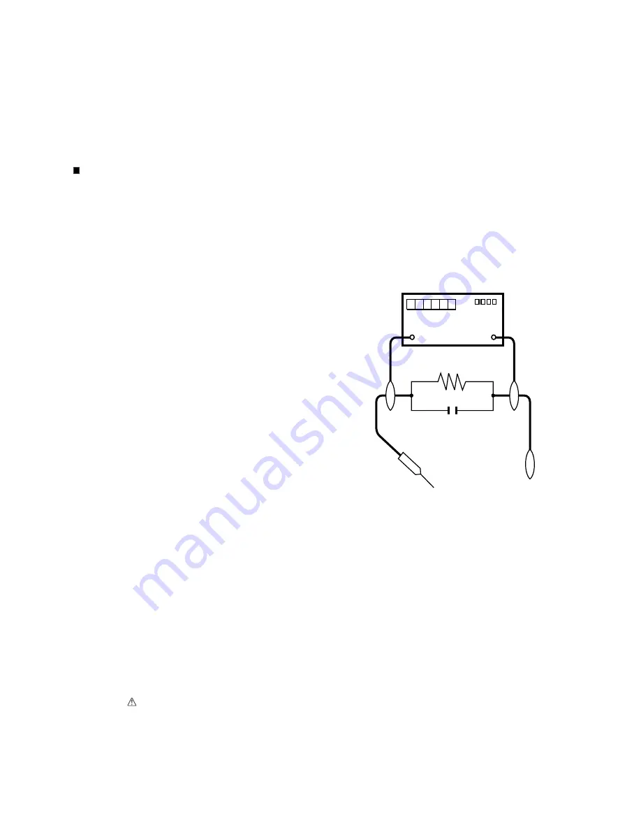
Us ing two clip leads , connect a 1.5k ohm, 10 watt res is tor paral-
leled by a 0.15 F capacitor in s eries with all expos ed metal cabinet
parts and a known earth ground, s uch as electrical conduit or elec-
trical ground connected to an earth ground.
•
Us e an AC voltmeter having with 5000 ohm per volt, or higher, s en-
s itivity or meas ure the AC voltage drop acros s the res is tor.
•
C onnect the res is tor connection to all expos ed metal parts having a
return to the chas s is (antenna, metal cabinet, s crew heads , knobs
and control s hafts , es cutcheon, etc.) and meas ure the AC voltage
drop acros s the res is tor.
All checks mus t be repeated with the AC cord plug connection
revers ed. (If neces s ary, a nonpolarized adaptor plug mus t be us ed
only for the purpos e of completing thes e checks .)
Any reading of 0.74 Vrms (this corres ponds to 0.5 mA rms AC .) or
more is exces s ive and indicates a potential s hock hazard which
mus t be corrected before returning the monitor to the owner.
///////////////////////////////////////////////////////////////////////////////////////////////////////////////////////////////////////////////////////////////////////////////////////////////////////////////////////////////////////////
S A F E T Y NOT IC E
Many electrical and mechanical parts in LC D colour televis ion have
s pecial s afety-related characteris tics .
T hes e characteris tics are often not evident from vis ual ins pection, nor
can protection afforded by them be neces s arily increas ed by us ing
replacement components rated for higher voltage, wattage, etc.
R eplacement parts which have thes e s pecial s afety characteris tics are
identified in this manual; electrical components having s uch features
are identified by "
" and s haded areas in the R eplacement P arts Lis t
and S chematic Diagrams .
F or continued protection, replacement parts mus t be identical to thos e
us ed in the original circuit.
T he us e of a s ubs titute replacement parts which do not have the s ame
s afety characteris tics as the factory recommended replacement parts
s hown in this s ervice manual, may create s hock, fire or other hazards .
///////////////////////////////////////////////////////////////////////////////////////////////////////////////////////////////////////////////////////////////////////////////////////////////////////////////////////////////////////////
S ervic e work s hould be performed only by qualified s ervic e tec hnic ians who are thoroughly familiar with all s afety c hec ks and the
s ervic ing guidelines whic h follow:
DV M
AC S C ALE
1.5k ohm
10W
T O E XP OS E D
ME T AL P AR T S
C ONNE C T T O
K NOWN E AR T H
G R OUND
0.15
µF
T E S T P R OB E
Summary of Contents for Aquos LC-60LE360X
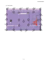
Page 12: ...LC 60 70LE360X 5 2 LC 70LE360X 6 6 6 6 6 6 6 6 6 6 6 6 6 6 6 6 6 6 6 6 6 6 6 6 6 6 6 6 7 ...
Page 34: ...LC 60 70LE360X 8 1 CHAPTER 8 SYSTEM BLOCK DIA GRAM 1 SYSTEM BLOCK DIAGRAM LC 60LE360X ...
Page 35: ...LC 60 70LE360X 8 2 2 SYSTEM BLOCK DIAGRAM LC 70LE360X ...
Page 61: ...LC 60 70LE360X 9 26 ...
Page 72: ...LC 60 70LE360X 11 ...

