4T-B70CJ1 TROUBLE SHOOTING 4 - 19
PAGE
NUMBER
PAGE
TITLE
ITEM
FUNCTION
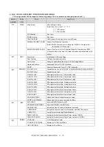
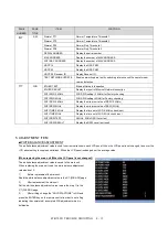
6/7
SW
Dimmer PT1
Dimmer Temperature Threshold 1
Dimmer PT2
Dimmer Temperature Threshold 2
Dimmer PD1
Dimmer Duty Threshold 1
Dimmer PD2
Dimmer Duty Threshold 2
SERIAL NUMBER
Display the serial number
MAC ADDRESS
Display the number of MAC ADDRESS
WIFI MAC ADDRESS
Display the number of MAC ADDRESS
HDCP1.4
Display the HDCP KEY
HDCP2.2
Display the HDCP KEY
HDCP2.2 Receiver ID
Display Receiver ID
TEST NETWORK UPDATE
Enable network update test by switching reference xml file name for new
version detection
7/7
WIFI
ETHER TEST
Ethernet Network Inspection
ETHER RESULT
Display the result of Ethernet Network Inspection
WIFI SSID 2.4GHz
WiFi SSID setting (2.4GHz) for Factory checking
WIFI SSID 5GHz
WiFi SSID setting (5GHz) for Factory checking
WIFI RSSI 2.4GHz
Display the minimum value of RSSI (2.4GHz)
WIFI RSSI 5GHz
Display the minimum value of RSSI (5GHz)
WIFI TIME 2.4GHz
Display the time out of WiFi 2.4GHz check (sec)
WIFI TIME 5GHz
Display the time out of WiFi 5GHz check (sec)
WIFI RSSI TEST
2.4GHz, 5GHz RSSI Level test
WIFI RSSI RESULT
Display the RSSI Level test result
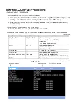
5. ADJUSTMENT ITEM
■WHITE BALANCE ADJUSTMENT
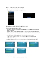
The white balance adjustment value is used to correct variations in each LCD panel. When the LCD panel is not changed, take over the
LCD panel setting to suppress variations. When the LCD panel is changed, set the average value.
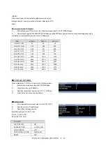
(When replacing the main unit [When the LCD panel is not changed])
The white balance adjustment value is saved to the main unit.
When replacing the main unit, read the white balance adjustment
value and set it.
1)
Before replacement the mainunit.
Read the white balance adjustment value in the 3/7 [WB ADJ] page.
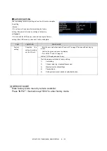
2)
After replacement the mainunit
Set the white balance adjustment value read in the step 1) in the
3/7 [WB ADJ] page.
3)
After writing, change the "ADJ DATA STORE" to ON and
press the ENTER key on the remote control in order to set a flag
indicating the completed / incomplete WB adjustment which is
heldinside.
Summary of Contents for Aquous 4T-B70CJ1U
Page 1: ...SHARP SERVICE MANUAL 4K ULTRA HD TV MODEL 4T B70CJ1U ...
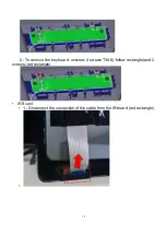
Page 8: ...6 2 Remove the 4 VESAscrews M6X12 3 Remove the 19 screws M3X8 at the rear cover area ...
Page 13: ...11 3 Remove 5 screws M3X6 in the main area Redcircle ...
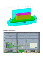
Page 18: ...16 2 Pull open the hook of IR Lens then take IR Board out WIRE DRESSING LAY OUT ...
Page 36: ...4T B70CJ1 TROUBLE SHOOTING 4 34 ...
Page 37: ...4T B70CJ1 TROUBLE SHOOTING 4 35 ...
Page 40: ...4T B70CJ1 TROUBLE SHOOTING 4 38 IC3501 3502 RH IXE098WJQZQ SAMSUNG K4B2G1646F BYMA DDR ...
Page 41: ...4T B70CJ1 TROUBLE SHOOTING 4 39 IC3101 RH IXE112WJQZQ SAMSUMG KLM4G1FETE B041 eMMC ...
Page 42: ...4T B70CJ1 TROUBLE SHOOTING 4 40 IC8102 RH IXE211WJQZY DIALOG AS3824E1 ZQFT LED Drive ...
Page 43: ...4T B70CJ1 TROUBLE SHOOTING 4 41 ...
Page 44: ...4T B70CJ1 TROUBLE SHOOTING 4 42 Q8101 8108 RH TXA102WJQZY Rohm SH8KA4TB ...
Page 45: ...4T B70CJ1 TROUBLE SHOOTING 4 43 CHAPTER 6 BLOCK DIAGRAM WIRING DIAGRAM 1 BLOCK DIAGRAM ...
Page 48: ...4T B70CJ1 TROUBLE SHOOTING 4 46 MAIN BOTTOM ...
Page 49: ...4T B70CJ1 TROUBLE SHOOTING 4 47 2 POWER UNIT PRINTED WIRING BOARD POWER TOP ...
Page 50: ...4T B70CJ1 TROUBLE SHOOTING 4 48 POWERBOTTOM ...
Page 52: ...4T B70CJ1 TROUBLE SHOOTING 4 50 CHAPTER 8 SCHEMATIC DIAGRAM 1 MAIN SCHEMATIC DIAGRAM ...
Page 53: ...4T B70CJ1 TROUBLE SHOOTING 4 51 ...
Page 54: ...4T B70CJ1 TROUBLE SHOOTING 4 52 ...
Page 56: ...4T B70CJ1 TROUBLE SHOOTING 4 54 4 KEY SCHEMATIC DIAGRAM ...
Page 59: ...4T B70CJ1 TROUBLE SHOOTING 4 57 2 CABINET PARTS ...
Page 60: ...4T B70CJ1 TROUBLE SHOOTING 4 58 3 SUPPLIED ACCESSORIES ...
Page 61: ...4T B70CJ1 TROUBLE SHOOTING 4 59 4 PACKING PARTS ...


