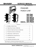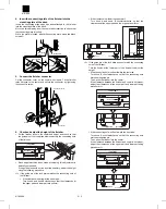
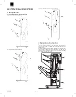
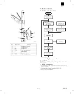
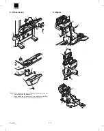
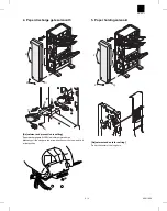
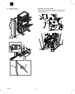
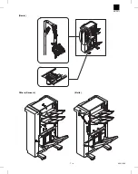

8. Elevator wires, top and bottom
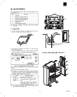
[Note] If the tray 3 is not at the upper limit position, turn the knurled
part on the shaft (A) in the sketch and move tray 3 to the
upper limit position.
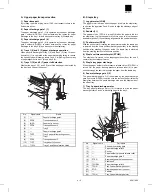
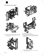
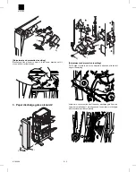
[Note] Remove the two screws 13) and:
1) Move the off-set tray to the lower limit position.
2) Turn the knurled part on the elevator worm gear shaft under the
elevator drive box so that the D-cut surface on the winding pulley
points upward.
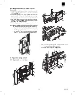
[Note] Remove the elevator wires (top, bottom) at the rear frame
side in the same manner.
2)
5)
2)
1)
1)
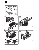
3)
4)
6)
5)
5)
5)
4)
8)
7)
7)
(A)
8)
8)
8)
8)
9)
8)
10)
11)
10)
10)
12)
13)
13)
12)
15)
16)
17)
18)
A
B
C
14)
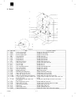
AR-FN3
8/19/1999
5 – 5
Summary of Contents for AR-FN3
Page 20: ...15 15 15 15 16 AR FN3 8 19 1999 5 7 ...
Page 27: ... Rollers Paper guides AR FN3 7 2 8 19 1999 ...
Page 28: ...AR FN3 8 19 1999 7 3 ...
Page 29: ... Gears Others Sensors Belts AR FN3 7 4 8 19 1999 ...
Page 51: ...3 Main PWB page arrangement 1 2 AR FN3 10 9 8 6 1999 ...
Page 52: ...Main PWB page arrangement 2 2 AR FN3 8 6 1999 10 10 ...