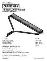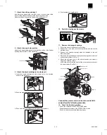
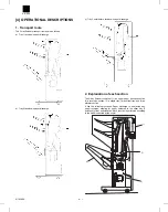
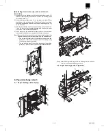
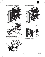
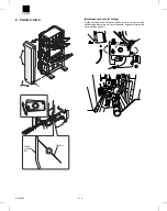
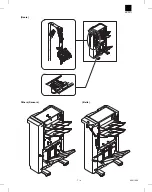
[Reinstalling elevator wires (top, bottom) at the front
frame side]
1) Insert both the top elevator wire 15) and bottom elevator wire 16)
into the elevator pulley drive shaft A. Secure the winding pulley
18) with the screw 17).
2) Hook the bottom elevator wire 16) on the lower wire roller B from
the left side of the winding pulley 18), without giving extra winding.
With the wire extended upward, hook the wire mounting spring 14)
on the wire hook.
3) Wind the top elevator wire 15) onto the winding pulley 18) and turn
3 and 3/4 turns in the clockwise direction and hook on the upper
wire roller C. Hold it stretched downward.
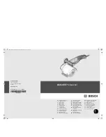
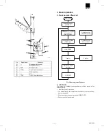
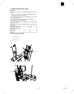
4) When setting the top and bottom elevator wires at the rear frame
side (see the sketch below), observe the following conditions:
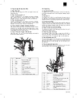
[Note] Observe the following conditions when setting elevator-wires
(top and bottom) at the rear frame side. See the sketch below.
•
The bottom elevator wire 16) should be hooked onto the
bottom wire roller B from the right side of the winding pulley
18) without giving extra winding.
•
The top elevator wire 15) should be wound onto the winding
pulley 18) 3 and 3/4 turns in the counterclockwise direction.
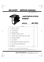
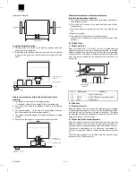
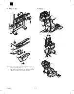
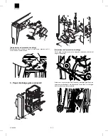
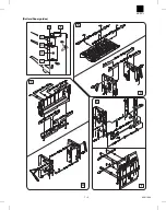
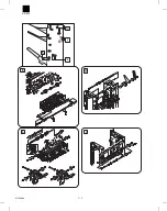
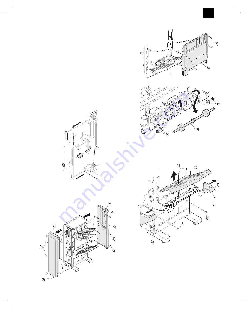
9. Paper discharge roller 3
9-1. Paper discharge roller 3 (top)
[Note] After removing the E-ring, slide the bearing A in the direction
A to remove the paper discharge roller 3.
9-2. Paper discharge roller 3 (bottom)
15)
16)
17)
18)
A
B
C
14)
AR-FN3
5 – 6
8/19/1999
Summary of Contents for AR-FN3
Page 20: ...15 15 15 15 16 AR FN3 8 19 1999 5 7 ...
Page 27: ... Rollers Paper guides AR FN3 7 2 8 19 1999 ...
Page 28: ...AR FN3 8 19 1999 7 3 ...
Page 29: ... Gears Others Sensors Belts AR FN3 7 4 8 19 1999 ...
Page 51: ...3 Main PWB page arrangement 1 2 AR FN3 10 9 8 6 1999 ...
Page 52: ...Main PWB page arrangement 2 2 AR FN3 8 6 1999 10 10 ...