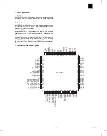
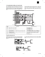
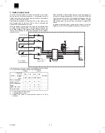
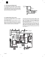


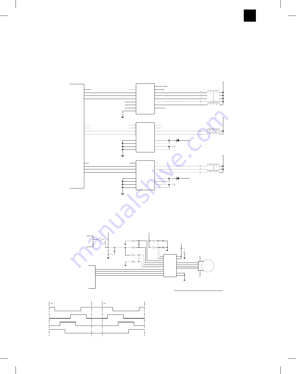
8. Solenoid and clutch drive circuit
The solenoid and clutch drive circuit uses non-inversion transistor
arrays TD62318AP (IC09, 12) which turn on the solenoids and
clutches when the input signal is at L; and an inversion transistor
array M63823P (IC14) which turns on the solenoids and clutches
when the input signal is at H.
The expansion I/O PG port which controls the solenoids and clutches
is an open collector type which becomes high impedance when reset-
ting and H output. For this reason, to turn on the solenoids and
clutches at L level, the non-inversion type TD62318AP is used for
driving the PG port. On the other hand, the expansion I/O’s PC port is
at L level at resetting. For this reason, for driving the PC port, the
inversion type M63823P which turns on the solenoids and clutches at
H level is used.
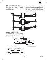
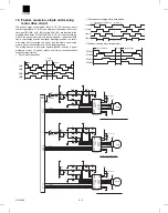
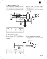
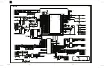
9. Jogger motor drive circuit
The jogger motor control signal (JMA, A/, B. B/) from the expansion
I/O (IC11) is input into the driver IC SLA7024MT, to drive the jogger
stepping motor which aligns the sheets sideways.
The driving method is unipolar, 1-2 phase excitement, constant-volt-
age method.
Here is the driving pattern for the jogger motor.
PF0
PF1
PF2
PF3
59
60
61 OG1SL/
62 OG3SL/
PC4
PC5
PC6
PC7
49
48 T12CL
47 OG2SL
46 STPDSL
PF4
PF5
PF6
PF7
63
64 T3PDSL/
1 PDCL/
2 STORCL/
1
2
3
4
5
6
7
8
13
4
5
12
13
4
5
12
14
11
6
3
14
11
6
3
16
15
14
13
12
11
10
9
I1
I2
I3
I4
I5
I6
I7
GND
COM
O1
O2
O3
O4
O5
O6
O7
IC14
IC09
IC12
TD62318AP
8
16
9
1
15
10
7
2
I4
I3
I2
I1
O4
O3
O2
O1
VCC2
VCC1
COM2
COM1
GND
GND
GND
GND
8
16
9
1
15
10
7
2
I4
I3
I2
I1
O4
O3
O2
O1
VCC2
VCC1
COM2
COM1
GND
GND
GND
GND
TD62318AP
+24V
RD16FB
RD16FB
ZD01
ZD02
+5V
+24V
+5V
+24V
T12CL/
OG2SL/
STPDSL/
OG1SL/
OG3SL/
T3PDSL/
PDCL/
STORCL/
+24V
+24V
+24V
I/O
(IC11)
T3PDSL
PDCL
STORCL
OG3SL
OG1SL
STPDSL
OG2SL
T12CL
PPSL/
PPSL
IC03(CPU)P46 PPSL
M63823P
IC03(CPU)P47 STSL
STSL/
PPSL
I/O
PC0
PC3
(IC11)
50
53
52
51
PC2
PC1
JGMA
JGMA/
JGMB
JGMB/
JGMA
JGMA/
JGMB
JGMB/
JGM
+24V
+24V
Here is the driving pattern for the jogger motor.
3
14
10
6
REFA
5
16
17
REFB
RSB
IN A
IN/A
IN B
IN/B
IC06
SLA7024MT
OUT A
OUT/A
OUT B
OUT/B
GA
GB
VSA
7
1
8
11
18
4
15
+24V
12
VSB
2
9
13
TDA
TDB
RSA
R137
47K
C134
470P
C130
470P
+5V
C04
R132
47K
C132
2200P
R08
1(1W)
R134
2.4K
R09
1(1W)
R136
2.4K
C133
2200P
R135
0.1U
C131
100
R133
910
+5V
CPU
(IC03)
R139
200
IC102
59
P61
6
11
TD62504F
47u/35
V
Alignment direction
Stop
Opening direction
JMA
JMB
JMA/
JMB/
AR-FN3
9 – 8
8/19/1999
Summary of Contents for AR-FN3
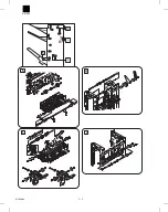
Page 20: ...15 15 15 15 16 AR FN3 8 19 1999 5 7 ...
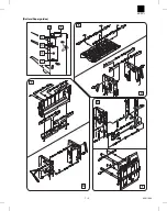
Page 27: ... Rollers Paper guides AR FN3 7 2 8 19 1999 ...
Page 28: ...AR FN3 8 19 1999 7 3 ...
Page 29: ... Gears Others Sensors Belts AR FN3 7 4 8 19 1999 ...
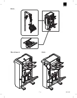
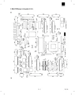
Page 51: ...3 Main PWB page arrangement 1 2 AR FN3 10 9 8 6 1999 ...
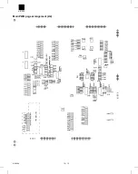
Page 52: ...Main PWB page arrangement 2 2 AR FN3 8 6 1999 10 10 ...