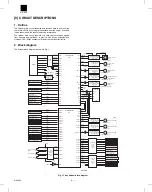
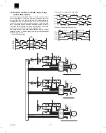


10 – 3
10 – 4
X1
12.228MHz
CNG-30
CNF-02
CNH-19
CNK-11
CNH-25
CNL-26
CNL-20
CNG-17
CNK-13
CNJ-08
CNG-08
CNG-05
CNC-01
CNC-02
CNC-03
CNL-18
CNF-06
CNL-14
CNF-12
CNG-32
CNJ-14
CNF-04
CNK-08
CNK-07
CNH-22
CNJ-02
CNL-23
CNK-16
CNJ-05
CNG-14
C107
C112
C140
0.1u
C119
0.1u
C169
C170
C171
C172
C173
C174
C175
C176
C148
C147
C146
C145
C144
C143
C141
IC14
BA12004B
COM
9
I1
1
I2
2
I3
3
I4
4
I5
5
I6
6
I7
7
GND
8
O1
16
O2
15
O3
14
O4
13
O5
12
O6
11
O7
10
ZD2
RD16FB
ZD1
RD16FB
C127
0.1u
CNG-11
CNH-14
R122
10k
CNF-10
CND-01
CNC-04
CND-02
CNK-19
R129
10k
C129
1000p
R123
10k
C128
0.1u
C2
47u/35V
+
CNE-06
R109
2.4k
C116
1000p
CNK-09
R108
10k
C115
1000p
CNM-04
R107
4.7k
C114
1000p
ZD5
RD6.2EB2
ZD4
RD6.2EB2
ZD3
RD6.2EB2
ZD6
RD6.2EB2
L102
ACB20120M-150-T
CNG-01
CNG-06
CNG-07
CNG-13
CNG-12
CNG-25
CNG-24
CNG-18
CNJ-07
CNJ-01
R124
10k
10K
10K
CNF-08
CNL-16
RN107
10kX4
RN106
10kX4
RN104
10kX4
L101
ACB20120M-150-T
IC101D
74HC14
9
8
CNB-03
F-DTR
CNB-01
F-TXD
CNB-02
F-RXD
CNB-04
F-DSR
C118
0.1u
CNB-05
F-RES
IC101C
74HC14
5
6
IC101B
74HC14
3
4
IC101A
74HC14
1
2
R115
1k
IC101F
74HC14
13
12
BRXX,RXX
10k
BRXX,RXX
10k
R18
240(1/4W)
R12
240(1/4W)
R16
240(1/4W)
R15
240(1/4W)
R17
240(1/4W)
R21
240(1/4W)
R24
240(1/4W)
R4
240(1/4W)
R25
240(1/4W)
R1
240(1/4W)
R140
R139
200
R111
10k
R112
10k
R110
10k
IC11
M66500FP
A2
35
A1
36
A0
37
D7
45
D6
44
D5
43
D4
42
D3
41
D2
40
D1
39
D0
38
/CS
32
/RD
30
/WR
31
RESET
33
PA7
21
PA6
22
PA5
23
PA4
24
PA3
25
PA2
26
PA1
27
PA0
28
PC3
53
PC2
52
PC1
51
PC0
50
PG3
57
PG2
56
PG1
55
PG0
54
PC4
49
PC5
48
PC6
47
PC7
46
PB0
13
PB1
14
PB2
15
PB3
16
PB4
17
PB5
18
PB6
19
PB7
20
PF0
59
PF1
60
PF2
61
PF3
62
PF4
63
PF5
64
PF6
1
PF7
2
PE0
4
PE1
5
PE2
6
PE3
7
PE4
8
PE5
9
PE6
10
PE7
11
VCC
3
VCC
29
GND1
34
GND2
58
GND3
12
CNG-02
CNG-20
CNJ-11
CNG-23
IC12
TD62318AP
I1
3
I2
6
I3
11
I4
14
GND
4
GND
5
GND
12
GND
13
O1
2
O2
7
O3
10
O4
15
COM1
16
COM2
9
VCC1
1
VCC2
8
IC9
TD62318AP
I1
3
I2
6
I3
11
I4
14
GND
4
GND
5
GND
12
GND
13
O1
2
O2
7
O3
10
O4
15
COM1
16
COM2
9
VCC1
1
VCC2
8
IC102
TD62504F
I1
1
I2
2
I3
3
I4
4
I5
5
I6
6
I7
7
G
8
O1
16
O2
15
O3
14
O4
13
O5
12
O6
11
O7
10
COM
9
IC7
27C010
A0
12
A1
11
A2
10
A3
9
A4
8
A5
7
A6
6
A7
5
A8
27
A9
26
A10
23
A11
25
A12
4
A13
28
A14
29
A15
3
A16
2
CE
22
OE
24
VPP
1
PGM
31
O0
13
O1
14
O2
15
O3
17
O4
18
O5
19
O6
20
O7
21
VCC
32
GND
16
RN105
10kX4
JP2(F-RES)
C106
RN101
10kX4
C108
C111
C110
C109
R131
200
IC101E
74HC14
11
10
BR11
10kX8
BR9
10kX8
RN103
10kX4
C142
BR8
10kX8
BR6
10kX8
BR5
10kX8
C153
0.1u
IC3
H8/3040
VCC
1
TIOCA3/TP8/PB0
2
TIOCB3/TP9/PB1
3
TIOCA4/TP10/PB2
4
TIOCB4/TP11/PB3
5
TOCXA4/TP12/PB4
6
TOCXB4/TP13/PB5
7
VSS
11
TXD0/P90
12
TXD1/P91
13
RXD0/P92
14
RXD1/P93
15
D0/P40
18
D1/P41
19
D2/P42
20
D3/P43
21
VSS
22
D4/P44
23
D5/P45
24
D6/P46
25
D7/P47
26
D8/P30
27
D9/P31
28
D10/P32
29
D11/P33
30
D12/P34
31
D13/P35
32
D14/P36
33
D15/P37
34
VCC
35
A0/P10
36
A1/P11
37
A2/P12
38
A3/P13
39
A4/P14
40
A5/P15
41
A6/P16
42
A7/P17
43
VSS
44
A8/P20
45
A9/P21
46
A10/P22
47
A11/P23
48
A12/P24
49
A13/P25
50
P26/A14
51
P27/A15
52
P50/A16
53
P51/A17
54
P52/A18
55
P53/A19
56
VSS
57
P60/WAIT
58
P61/BREQ
59
P62/BACK
60
STBY
62
RES
63
NMI
64
VSS
65
EXTAL
66
XTAL
67
VCC
68
P63/AS
69
P64/RD
70
P65/HWR
71
P66/LWR
72
MD0
73
MD1
74
MD2
75
AVCC
76
VREF
77
P70/AN0
78
P71/AN1
79
P72/AN2
80
P73/AN3
81
P74/AN4
82
P75/AN5
83
P76/AN6/DA0
84
P77/AN7/DA1
85
AVSS
86
P80/RFSH/IRQ0
87
P82/CS2/IRQ2
89
P83/CS1/IRQ3
90
P84/CS0P84/
91
VSS
92
CS3/RAS/IRQ1
88
TEND0/TCLKA
93
TEND1/TCLKB
94
TIOCA0/TCLKC
95
TIOCB0/TCLKD
96
TIOCA1/A23
97
TIOCB1/A22
98
TIOCA2/A21
99
TIOCB2/A20
100
DREQ0/TP14/PB6
8
ADTRG/DREQ1
9
RESO
10
IRQ4/SCK0/P94
16
IRQ5/SCK1/P95
17
S-CLK
61
Q101
CRT1N141C
B
10k
10k
CNG-26
(RVPD/)
D103
3
1
2
D104
3
1
2
D105
3
1
2
D101
3
1
2
D102
3
1
2
JP102
0J 1/8W
JP101
0J 1/8W
Q102
CRT1N141C
B
10k
10k
R130
4.7k
R126
4.7k
R114
4.7k
C120
1000p
C117
1000p
CP2
CHECK POINT
CP3
CHECK POINT
CP4
CHECK POINT
CP1
CHECK POINT
CNF-07,CNL-15
+24V3
R125
4.7k
R113
4.7k
CNH-16
BR3
10kX6
C113
BR1
10kX8
RN102
10kX4
READY/
PSHP1
STORHP
STUHP
T2PF/
STND
FMDIR
T3OMA
T3OMA/
T3OMB
T3OMB/
PMA
PMA/
PMB
STHP/
PMB/
ROMCS/
N.C
EXPCS/
N.C
OFHP
EVRE/
STND
RVPD/
T2PF/
STUMA/
STUHP
STUMB
STORHP
STUMB/
PSHP1
READY/
OFMA
JGHP
OFMB
PPSL
STSL
D0
D1
MD0
D2
LWR/
D3
HWR/
D4
RD/
XTAL
D5
AS/
D6
D7
EXTAL
A0
A1
A2
RES/
A3
STBY/
A4
N.C
A5
A6
A7
A3
A4
A8
A19
A5
A9
A18
A6
A10
A17
A7
A11
A16
A8
A12
A15
A15
A15
A9
A13
A14
A14
A14
A10
A11
A12
A13
A14
A15
(INGSL/)
(RRSL/)
T3OD/
NCTS/
OG2SL/
+24V3
STPDSL/
EVRE
FMPWM/
FMRE
RESO/
FMRE
STHP/
OFHP
COM1
COM2
COM3
COM4
COM5
COM7
COM8
COM6
COM10
COM9
PPSL/
DKRCL/
D0
+24V1
T3PDSL/
D4
OG3SL/
PDCL/
N.C.
PDCL/
OG3SL/
T12CL
D4
D6
D6
D7
A1
D5
INPD/
D5
OG1SL/
T3PDSL/
+24V1
DKRCL/
A0
D2
PFD3/
D3
N.C.
N.C.
(PFD1/)
D0
D1
A1
(RRSL/)
(INGSL/)
A2
D1
D7
A2
+24V2
+24V2
A0
STPDSL
D2
D3
PFD2/
STORCL/
JGMB
PFD4/
N.C.
OG1SL/
STORCL/
JGMB/
DKRHP
OG2SL
T3PDHP/
JGMA
STSL/
PFD4/
PFD3/
PFD2/
JGMA/
JMPD
PMPD
F-TXD
F-RXD
F-DTR
DSW2
DSW3
DSW1
DSW2
PWD1
DSW1
N.C
T1PF/
NCTS/
STID2/
T1PF/
STPD/
STPD/
T3DN
LSTS/
LSTS/
T3UP
T3DN
STID2/
STID/
T3UP
STID/
T3OD/
INPD/
T3PDHP/
(PFD1/)
DKRHP
+24V
DSW3
PWD1
(SPSL)
PMPD
VCC
VCC
VCC
VCC
VCC
VCC
VCC
VCC
VCC
STUMA
JGHP
GND
GND
GND
GND
GND
GND
MD1
MD2
GND
GND
GND
JMPD
F-DSR
RVMB/
RVMB
RVMA/
RVMA
STMB
STMA
EMB
EMA
T3MPD
T3MPD
(SPSL/)
T12CL/
+24V
+5V
+5V
+24V
+24V
+24V3
+5V
+5V
+5V
+5V
+24V
T3OMA
T3OMA/
T3OMB
T3OMB/
PMA
PMA/
PMB
A16
FMDIR
EVRE/
HWR/
RD/
A16
EMA
EMB
STMA
STMB
ROMCS/
RD/
PMPD
PMPD/
PMPD
RES/
EVRE/
ROMCS/
EXPCS/
STUMA
STUMA/
STUMB/
STUMB
PPSL
FMPWM/
OFMB
OFMA
STSL
PMB/
CPU+5V
CPU+5V
EXPCS/
RES
RD/
HWR/
JGMA/
JGMA
JGMB/
JGMB
JMPD
T3MPD/
RES/
RES
CPUGND
JMPD
JMPD/
T3MPD
T3MPD
RVMA
RVMA/
RVMB
RVMB/
TP15/PB7
P81/
PA0/TP0/
PA1/TP1/
PA2/TP2/
PA3/TP3/
PA4/TP4/
PA5/TP5/
PA6/TP6/
PA7/TP7/
1000p X 8
1000p X 8
(1-3C)
(1-3D)
(1-3C)
(1-3C)
(1-6B)
(1-6B,7B)
(1-7B)
(2-4B)
(2-3C)
(1-6C)
(1-3D)
(1-3C)
(1-6C)
(1-7A)
(2-4C)
(2-6D)
(1-7B)
(1-6B)
(1-7A)
PPSL
(1-6C)
STSL
(1-6C)
(1-3C)
(2-8B)
(1-3C)
1000p X 8
(INPD/)
(PFD2/)
(PFD3/)
(PFD4/)
(T1PF/)
(T2PF/)
(PFD1/)
(RVPD/)
(T3OD/)
(STID/)
=
1
note
BR2,3,5,7,8,9,
R102,103,104
2.3.4...
=
1
OTHER
BR,R
(1-7A)
(2-7A)
(2-8C)
FOR COUGAR-50
ONLY
FOR TIGER ONLY
(1-3C)
(1-6B)
2.3.4....
(2-7B)
(2-7C)
(2-7C)
(2-7C)
(2-7C)
(2-7B)
(2-7B)
(2-7B)
(1-4A)
(2-6B)
(2-7A)
(2-7A)
(2-7A)
(2-7A)
(2-6B)
(1-4A)
(2-7A)
(2-7A)
(2-7A)
(2-4B)
(2-3C)
10kX8
BR2
10kX8
BR4
(1-3C)
(2-8A)
FOR TIGER ONLY
(1-7A)
(1-3C)
MC2840 X 5
(2-5C)
(2-5C)
(2-5C)
(2-5C)
(RVPD/)
READY/
PSHP1
STORHP
STUHP
T2PF/
STND
JGHP
8
3
4
5
6
7
9
2
3
3
2
1
1
4
2
4
6
6
7
8
8
5
7
5
8
3
4
5
6
7
9
2
2
2
3
4
4
1
3
1
7
7
6
5
5
8
6
8
E
E
BR7
10k 6
X
2
2
3
4
4
1
3
1
7
7
6
5
5
8
6
8
3
8
7
6
5
4
2
9
2
8
7
6
5
4
3
6
5
4
3
2
5
4
3
2
4 3 2 1
2
3
4
5
6
7
8
9
9
8
7
6
5
4
3
2
9
8
7
6
2
4
3
5
8
7
6
5
4
3
2
1
8
7
6
5
4
3
2
1
D
C
B
A
D
C
B
A
1/3
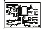
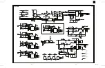
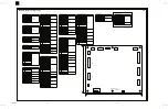
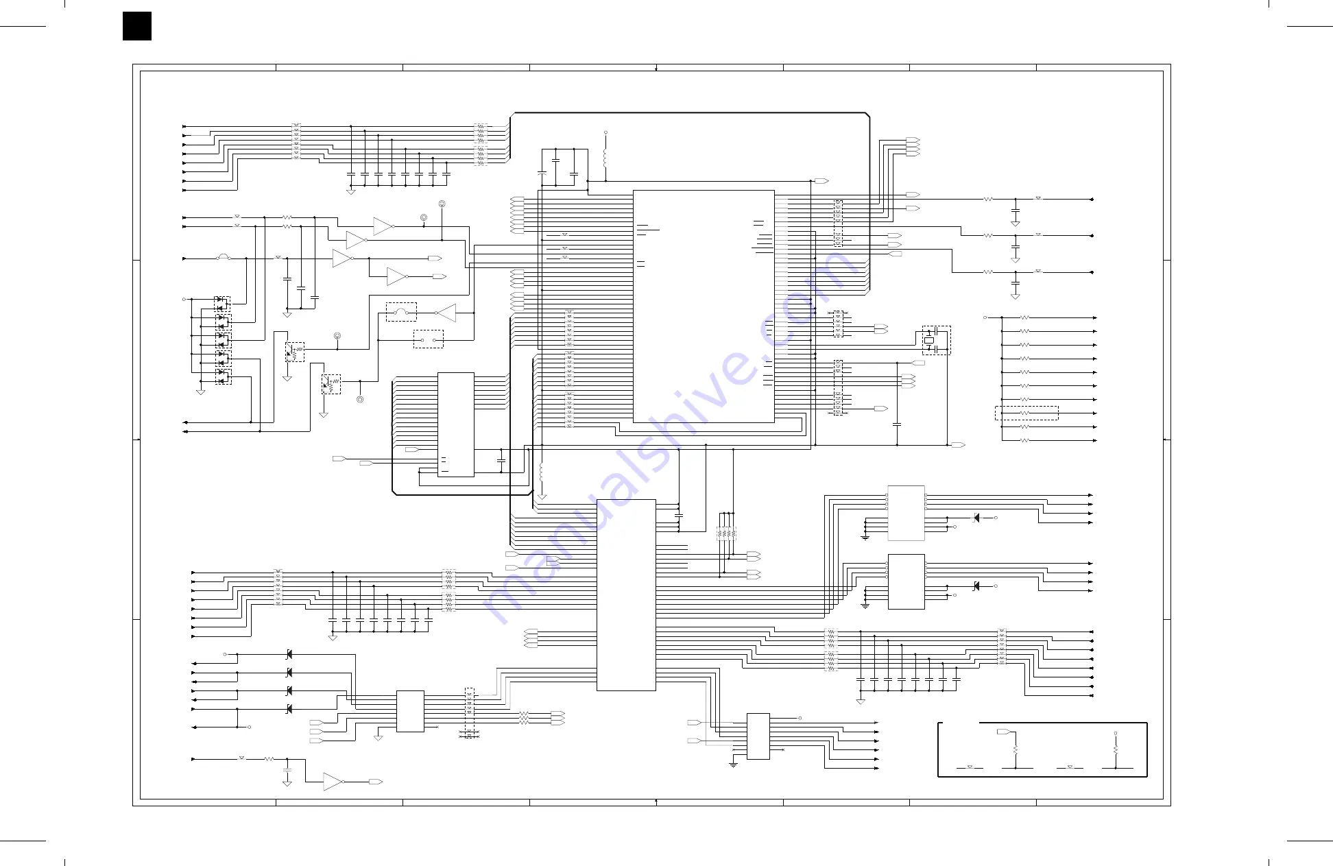
2. Main PWB
9
8
7
6
5
4
3
2
100
AR-FN3
8/6/1999
Summary of Contents for AR-FN3
Page 20: ...15 15 15 15 16 AR FN3 8 19 1999 5 7 ...
Page 27: ... Rollers Paper guides AR FN3 7 2 8 19 1999 ...
Page 28: ...AR FN3 8 19 1999 7 3 ...
Page 29: ... Gears Others Sensors Belts AR FN3 7 4 8 19 1999 ...
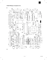
Page 51: ...3 Main PWB page arrangement 1 2 AR FN3 10 9 8 6 1999 ...
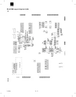
Page 52: ...Main PWB page arrangement 2 2 AR FN3 8 6 1999 10 10 ...