background image

: Jan. 9 2004

1

AR-LC6  ELECTRICAL SECTION  8 - 2

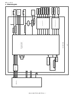
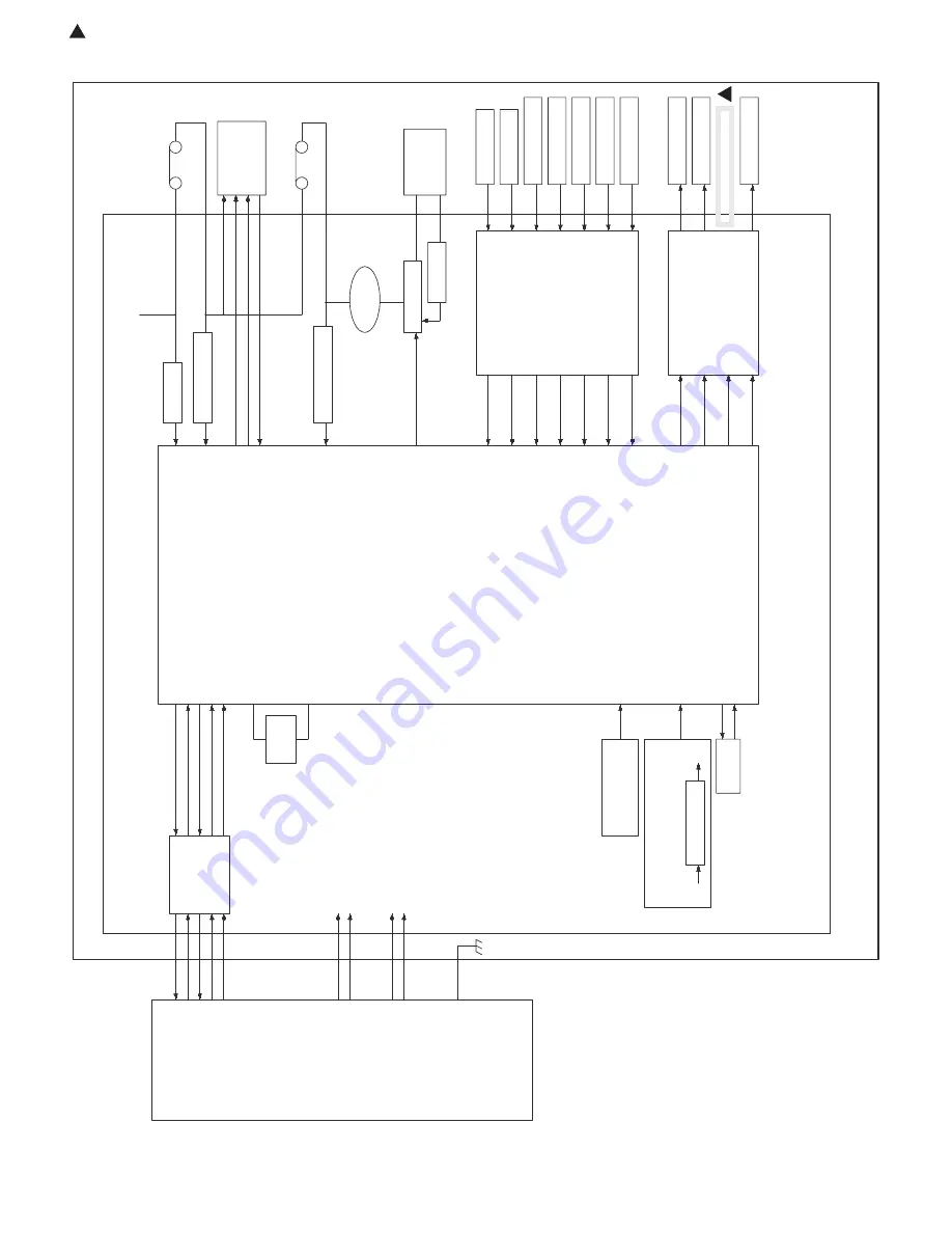
2. Block diagram

EEPROM

RXD-LCC

DSR-LCC

TXD-LCC

DTR-LCC

RES-LCC

GND2

5V

24V

GND1

F.G.

Main unit

Comm

unication

b

uff

er circuit

Xtal

7.37MHz

24V monitor

circuit

24V

Upper door open/close

s

w

itch (LOSW)

Upper limit s

witch (LLSW)

Lift motor (LLM)

Upper limit sensor

(LUD)

Lo

w

er limit sensor

(LLD)

P

aper presence/empty

sensor (LPED)

P

a

per e

xit sensor (L

TD)

Main unit connection

sensor (L

T

O

D)

Cassette sensor (LCD)

Remaining quantity

sensor (LRE)

P

aper f

eed clutch

(LPFCL)

T

ranspor

t clutch

(L

TCL)

P

a

per f

e

ed solenoid

(LPSL)

T

ranspor

t motor

(L

TM)

Upper door detection

monitor circuit

Upper limit detection

monitor circuit

P

oly-s

witch 1.1A

Lift motor dr

iv

e

circuit

Current limit

circuit

Sensor input circuit

Solenoid/clutch dr

iv

e circuit

CPU (HD64F3644H)

Ar

ithmetic section

On-board wr

ite circuit

P

o

w

er 12V circuit

Comm

unication wr

ite circuit

24V

12V

LCC MAIN PWB

LCC

1

Summary of Contents for AR-LC6

Page 1: ...o be used for after sales service only The contents are subject to change without notice SERVICE MANUAL CONTENTS CODE 00ZARLC6 A2E DIGITAL COPIER PRINTER MULTIFUNCTIONAL SYSTEM OPTION LARGE CAPACITY TRAY MODEL AR LC6 1 OUTLINE OF THE PRODUCT 1 1 2 SPECIFICATIONS 1 1 3 INTERNAL CONSTRUCTION 3 1 4 OPERATIONAL DESCRIPTIONS 4 1 5 DISASSEMBLY ASSEMBLY MAINTENANCE 5 1 6 ADJUSTMENT 6 1 7 TROUBLESHOOTING ...

Page 2: ... 105g m2 16 28lbs Paper capacity 3 500 sheets 80g m2 Remaining paper detection Enable Paper empty and 6 steps Paper feed system Front loading paper feed from the upper section Tray lift time Up max 15sec Down max 5sec Power consumption Normal operation 26 4W or less Lift up 42W or less Power source 24V and 5V are supplied from the main unit External dimensions 376 W x 545 5 D x 517 5 H mm Occupyin...

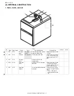
Page 3: ...s the paper feed table When the lower limit sensor is ON H level When the upper limit sensor is ON L level 3 LTCL LTCL Transport clutch Controls ON OFF of the transport roller 4 LPFCL LPFCL Paper feed clutch Controls ON OFF of the paper feed roller When paper feed is started H level After starring transport pickup OFF it is turned OFF by the timer 5 LPSL LPSL Paper feed solenoid Presses the paper ...

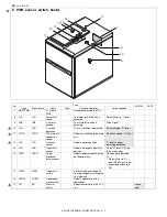
Page 4: ...nnection to the main unit When connected H level 12 LTD LTD Transport sensor Detects paper transport L level at paper remaining detection 13 LUD LUD Upper limit sensor Detects the paper upper limit position When H level ON the lift up motor stops 14 LPED LPED Paper presence empty sensor Detects paper presence empty on the paper tray When paper is detected H When lifting up if L with LRE 800 pulse ...

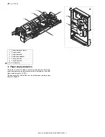
Page 5: ...clutch LTCL the paper feed clutch LPFCL and the paper feed solenoid LPSL at the following timing When the transport clutch LTCL is turned ON with the transport motor LTM ON rotating the transport roller rotates When the paper feed clutch LPFCL is turned on under this state the paper feed roller and the take up roller rotate When the paper feed solenoid LPSL is turned ON the take up roller is pushe...

Page 6: ...ng paper feed operation paper presence empty is detected by the paper presence empty sensor LPED When paper empty is detected in the tray during paper feeding paper feeding is stopped 3 4 5 1 2 6 7 1 1 Paper feed roller clutch 2 Take up roller 3 Paper feed roller 4 Paper feed solenoid 5 Transport clutch 6 Transport motor 7 Lift up motor 1 ...

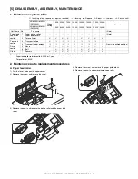
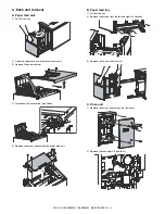
Page 7: ...pen the upper cover 2 Remove the screw and remove the sheet 3 Remove the pawl and remove the pickup roller and the paper feed roller 4 Remove the screw and remove the paper guide block 5 Remove the pawl and remove the reverse roller AR M550U M550N PM 250K When calling 250K 500K 750K 1000K 1250K 1500K 1750K 2000K Remark AR M620U M620N PM 300K 300K 600K 900K 1200K 1500K 1800K 2100K 2400K Unit name N...

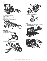
Page 8: ...ews 3 Remove the upper cabinet 4 Disconnect the connectors 2 positions 5 Remove the screw and remove the paper feed unit B Paper feed tray 1 Pull out the tray 2 Remove the screws from the left and right rail sections 3 Remove the tray unit from the rail C Drive unit 1 Remove the screw and remove the rear cover 2 Remove the connectors 2 positions ...

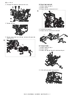
Page 9: ...tor 3 Remove the screw and remove the motor B Lift motor 1 Remove the drive unit 2 Remove the E ring and remove the parts 3 Remove the screw and remove the cover 4 Remove the screw and remove the lift motor 5 Remove the ring and remove the pulley C Clutch 1 Remove the paper feed unit Refer to 3 Each unit removal 2 Remove the screw and remove the cover 3 Remove the E ring and remove the parts ...

Page 10: ... paper feed transport clutch D Paper feed solenoid 1 Remove the paper feed unit 2 Remove the cover 3 Remove the screw and remove the unit 4 Disconnect the connector 5 Remove the screw and remove the solenoid E Torque limiter 1 Remove the paper feed unit 2 Remove the cover 3 Remove the E ring and the screw and remove the parts 4 Lift the shaft and remove the torque limiter 1 1 ...

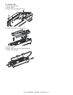
Page 11: ...sport roller 1 Remove the paper feed unit 2 Remove the cover 3 Remove the spring and remove the screw 4 Remove the plate cover and remove the lever 5 Remove the clutch 6 Remove the screw and the E ring and remove the parts 7 Remove the transport roller ...

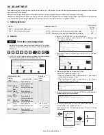
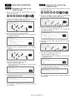
Page 12: ...lue is in the range of 0 3mm When the value is in the above range press CA key to terminate the simulation Job No Adjustment item list Simulation to be used ADJ 1 Print off center adjustment 50 10 ADJ 2 Resist amount adjustment ADJ 2A Adjustment in the resist amount adjustment mode 51 2 ADJ 2B Adjustment in the print lead edge adjustment mode 50 5 ADJ 1 Print off center adjustment Adjustment posit...

Page 13: ...Resist amount adjustment ADJ 2A Adjustment in the resist amount adjustment mode P C 5 1 2 1 SIMULATION 51 2 RESIST TIMING ADJUSTMENT SELECT 0 14 AND PRESS START 0 TRAY SELECT 1 1 PRINT START 2 TRAY1 50 3 TRAY2 50 4 TRAY3 50 5 TRAY4 50 6 BPT 50 7 LCC 50 8 ADU 50 9 SPF TOP 50 10 SPF HIGH 50 11 SPF LOW 50 12 SPF FEED TOP 50 13 SPF FEED HIGH 50 14 SPF FEED LOW 50 1 SIMULATION 51 2 RESIST TIMING ADJUST...

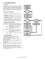
Page 14: ...When the machine recognizes a trouble it stops the operation and dis plays the trouble message A warning message is displayed when a consumable part life is nearly expired or is expired When a warning message is displayed the machine may be or may not be stopped The trouble messages and the warning messages are displayed by the LCD Some trouble messages are automatically cleared when the trouble i...

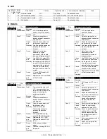
Page 15: ...he connector and the harness of the communication line Connect the connector properly Replace the harness Case 2 Cause LCC main PWB trouble control PWB PCU trouble Check and Remedy Replace the LCC PWB Replace the control PWB PCU Case 3 Cause Malfunction caused by noises Check and Remedy Cancel by turning OFF ON the power Main Sub Title Transport motor trouble U6 21 Display Message Phenomenon Detai...

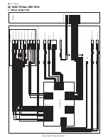
Page 16: ...TOD 20 22 9 B24B PHDSS B 2 8 LPED 5V 23 5VR 24 3 LTD 5V 19 GND2 LPFCL 21 GND2 NC 3 2 1 COM LOSW ON Upper open close switch 15 16 17 18 13 14 13 14 15 16 17 18 Paper feed unit 1 1 2 2 3 3 2 1 3 4 5 6 24V 24V LOSW GND2 CN D B10B PHDSS B 2 1 1 2 Heater 7 9 10 GND2 GND2 8 24V LOSW GND2 GND2 4 12 ELP 12V 5 Earth 5V 3 2 1 LCD LCD GND2 Cassette detection ELP 02V ELR 02V 1 3 ELP 03V 2 3 2 1 3 2 1 2 3 1 EL...

Page 17: ...ce empty sensor LPED Paper exit sensor LTD Main unit connection sensor LTOD Cassette sensor LCD Remaining quantity sensor LRE Paper feed clutch LPFCL Transport clutch LTCL Paper feed solenoid LPSL Transport motor LTM Upper door detection monitor circuit Upper limit detection monitor circuit Poly switch 1 1A Lift motor drive circuit Current limit circuit Sensor input circuit Solenoid clutch drive c...

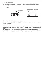
Page 18: ...tional one it is apt to keep the soldering iron in contact with the PWB for longer time This may cause land separation or may exceed the heat resistive temperature of components Use enough care to separate the soldering iron from the PWB when completion of soldering is confirmed Since lead free solder includes a greater quantity of tin the iron tip may corrode easily Turn ON OFF the soldering iron...

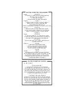
Page 19: ...sfara vid felaktigt batteribyte Använd samma batterityp eller en ekvivalent typ som rekommenderas av apparattillverkaren Kassera använt batteri enligt fabrikantens instruktion German Achtung Explosionsgefahr bei Verwendung inkorrekter Batterien Als Ersatzbatterien dürfen nur Batterien vom gleichen Typ oder vom Hersteller empfohlene Batterien verwendet werden Entsorgung der gebrauchten Batterien nu...

Page 20: ...s 98 Windows Me Windows NT 4 0 Windows 2000 and Windows XP are trademarks or copyrights of Microsoft Corporation in the U S A and other countries IBM and PC AT are trademarks of International Business Machines Corporation Acrobat Reader Copyright 1987 2002 Adobe Systems Incorporated All rights reserved Adobe the Adobe logo Acrobat and the Acrobat logo are trademarks of Adobe Systems Incorporated A...

Reviews: