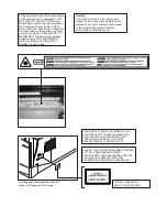
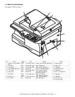
background image

CONTENTS

Parts marked with “

” are important for maintaining the safety of the machine. Be sure to replace these parts

with the replacement parts specified to maintain the safety and performance of the machine.

SHARP CORPORATION

This document has been published to be used
for after sales service only.
The contents are subject to change without notice.

SERVICE MANUAL

CODE : 00ZARM155/A1E

DIGITAL MULTIFUNCTIONAL 
SYSTEM

AR-M150
AR-M155

MODEL

AR-M155X

(AR-M155)

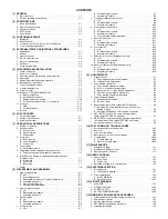
[ 1 ]  GENERAL . . . . . . . . . . . . . . . . . . . . . . . . . . . . . . . . . . . . . . . . . . . 1 - 1

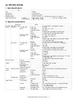
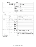
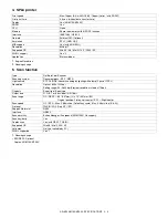
[ 2 ]  SPECIFICATIONS. . . . . . . . . . . . . . . . . . . . . . . . . . . . . . . . . . . . . 2 - 1

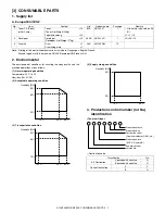
[ 3 ]  CONSUMABLE PARTS. . . . . . . . . . . . . . . . . . . . . . . . . . . . . . . . . 3 - 1

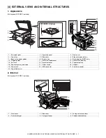
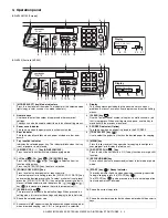
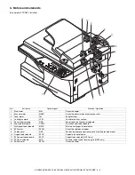
[ 4 ]  EXTERNAL VIEWS AND INTERNAL STRUCTURES  . . . . . . . . . 4 - 1

[ 5 ]  UNPACKING AND INSTALLATION  . . . . . . . . . . . . . . . . . . . . . . . 5 - 1

[ 6 ]  COPY PROCESS  . . . . . . . . . . . . . . . . . . . . . . . . . . . . . . . . . . . . . 6 - 1

[ 7 ]  OPERATIONAL DESCRIPTIONS . . . . . . . . . . . . . . . . . . . . . . . . . 7 - 1

[ 8 ]  DISASSEMBLY AND ASSEMBLY  . . . . . . . . . . . . . . . . . . . . . . . . 8 - 1

[ 9 ]  ADJUSTMENTS  . . . . . . . . . . . . . . . . . . . . . . . . . . . . . . . . . . . . . . 9 - 1

[10] TEST COMMAND, TROUBLE CODES. . . . . . . . . . . . . . . . . . . . 10 - 1

[11]  MAINTENANCE. . . . . . . . . . . . . . . . . . . . . . . . . . . . . . . . . . . . . . 11 - 1

[12]  USER PROGRAM . . . . . . . . . . . . . . . . . . . . . . . . . . . . . . . . . . . . 12 - 1

[13]  ELECTRICAL SECTION . . . . . . . . . . . . . . . . . . . . . . . . . . . . . . . 13 - 1

[14]  CIRCUIT DIAGRAM  . . . . . . . . . . . . . . . . . . . . . . . . . . . . . . . . . . 14 - 1

[15]  FIRMWARE DOWNLOAD PROCEDURES. . . . . . . . . . . . . . . . . 15 - 1

Summary of Contents for AR-M150 Online

Page 1: ... change without notice SERVICE MANUAL CODE 00ZARM155 A1E DIGITAL MULTIFUNCTIONAL SYSTEM AR M150 AR M155 MODEL AR M155X AR M155 1 GENERAL 1 1 2 SPECIFICATIONS 2 1 3 CONSUMABLE PARTS 3 1 4 EXTERNAL VIEWS AND INTERNAL STRUCTURES 4 1 5 UNPACKING AND INSTALLATION 5 1 6 COPY PROCESS 6 1 7 OPERATIONAL DESCRIPTIONS 7 1 8 DISASSEMBLY AND ASSEMBLY 8 1 9 ADJUSTMENTS 9 1 10 TEST COMMAND TROUBLE CODES 10 1 11 ...

Page 2: ... inserting wedges or other items into the switch slot LASER WAVE LENGTH 770 795nm Pulse times 10 24µsec Out put power 0 15mW 0 01mW CAUTION INVISIBLE LASER RADIATION WHEN OPEN AND INTERLOCKS DEFEATED AVOID EXPOSURE TO BEAM VORSICHT UNSICHTBARE LASERSTRAHLUNG WENN ABDECKUNG GEÖFFNET UND SICHERHEITSVERRIEGELUNG ÜBERBRÜCKT NICHT DEM STRAHL AUSSETZEN VARO AVATTAESSA JA SUOJALUKITUS OHITETTAESSA OLET A...

Page 3: ...able only to the 220V model 230V model and 240V model VAROITUS LAITTEEN KÄYTTÄMINEN MUULLA KUIN TÄSSÄ KÄYTTÖOHJEESSA MAINITULLA TAVALLA SAATTAA ALTISTAA KÄYTTÄJÄN TURVALLISUUSLUOKAN 1 YLITTÄVÄLLE NÄKYMÄTTÖMÄLLE LASERSÄTEILYLLE VARNING OM APPARATEN ANVÄNDS PÅ ANNAT SÄTT ÄN I DENNA BRUKSANVISNING SPECIFICERATS KAN ANVÄNDAREN UTSÄTTAS FÖR OSYNLIG LASERSTRÅLNING SOM ÖVERSKRIDER GRÄNSEN FÖR LASERKLASS ...

Page 4: ...transport section 8 9 A List 8 9 B Disassembly procedure 8 9 C Assembly procedure 8 14 6 Manual paper feed section 8 15 A List 8 15 B Disassembly procedure 8 15 C Assembly procedure 8 16 D Pressure plate holder attachment 8 16 7 Rear frame section 8 17 A List 8 17 B Disassembly procedure 8 17 C Assembly procedure 8 17 8 Power section 8 18 A List 8 18 B Disassembly procedure 8 18 C Assembly procedu...

Page 5: ... function or no option available Opt Option 2 Note for servicing and handling When the main unit power is repeatedly turned OFF ON rapidly for about 1sec the IC OA982 on the MCU PWB may malfunction to cause an error E1 00 Communication error which does not boot the machine In case of this error the blank display is kept for several tens seconds and then E1 00 is displayed on the panel display Coun...

Page 6: ...50 sheets Kinds Standard paper specified paper recycled paper Remark User adjustment of front paper guide available Multi bypass paper feed section Paper size 8 1 2 x 14 8 1 2 x 11 8 1 2 x 5 1 2 3 1 2 x 5 1 2 Landscape Paper weight 14 34 5 lbs Paper feed capacity 50 sheets Kinds Standard paper specified paper recycled paper OHP Label Envelop Single copy Remark User adjustment of side paper guide a...

Page 7: ... steps in 1 increments Manual steps text photo 5 steps Copy speed First copy time Tray paper feed 9 6 sec Pre heat mode 25 sec Auto power shut off mode 40 sec A4 or Letter 100 Auto Exposure AB system A4 Landscape Copy speed CPM Same size 15 Enlargement 15 Reduction 15 AB system B5 Landscape Copy speed CPM Same size 15 Enlargement 15 Reduction 15 Inch system 8 1 2 x 14 Landscape Copy speed CPM Same...

Page 8: ...atus window Type Flat Bed Color Scanner Scanning system Document glass SPF RSPF Light source 3 CCDs RGB sensor scanning by lighting white lamp 2 pcs of CCFL Resolution Optical 600 x 1200dpi Setting range 50 9600dpi Preview resolution is fixed at 75dpi Originals Sheet type Book type Output data R G B 1 or 8 bits pixel A D 16bit Scan range OC RSPF 8 5 297mm L x 14 431mm W Original position Platen Le...

Page 9: ... control number lot No identification Toner cartridge Destination code No Item Content Life Product name Package Remark 1 Toner CA Black with IC chip Toner Toner Net Weight 243g 10 80K AR 152LT 1 Life setup is based on A4 6 LT T 10 Polyethylene bag 10 2 Developer Developer Developer Net Weight 170g 10 250K AR 152LD 1 LD DV 10 3 Drum kit Drum 1 25K AR 152DM 10 Drum fixing plate 1 Humidity RH 85 60 ...

Page 10: ...g immediately after removing it from the copier Note Never carry exposed Toner unit Be sure to put it in the collection bag Division No Option 2 Packed with machine 3 Production month Production day Destination code Dealer distributor OEM etc Production place SOCC Fixed to B End digit of year Version No X 0001 1 9 Ver A 1 Production month 1 9 Jan Sep 0 Oct X Nov Y Dec Serial number of month Fixed ...

Page 11: ... 8 Bypass tray 9 Reversing tray RSPF only 10 Original guides 11 Document feeder cover 12 Document feeder tray 13 Exit area 14 Document cover 15 Paper output tray 16 Paper output tray extension 17 Power switch 18 Handles 19 Power cord 20 USB connector 21 Parallel connector 22 Paper holder arm 1 Front cover 2 Side cover 3 Fusing unit release lever 4 Transfer charger 5 Charger cleaner 6 Photoconducti...

Page 12: ...omatic two sided copying mode 12 E SORT SP FUN key Press to select the sort function 2 IN 1 copy function or margin shift function 13 key key OK ENTER key Press the key or key to select an item in a function setting menu Press the OK ENTER key to enter a selection 14 EXPOSURE key Use to switch from auto exposure adjustment to text mode or photo mode 15 ZOOM COPY RATIO key Press to select an enlarg...

Page 13: ...olenoid RRS Resist roller rotation control solenoid 6 Paper feed solenoid CPFS1 Cassette Paper feed solenoid 1 7 Multi paper feed solenoid MPFS Multi manual pages feed solenoid 8 SPF motor SPFM Drives the single pass feeder 9 Duplex motor DMT Devices the duplex paper transport section Duplex model only 10 Original feed solenoid SPUS Original pick up solenoid 11 SPF paper feed solenoid SPFS Origina...

Page 14: ...n 2 L at paper pass 4 Cassette detection switch CED1 Micro switch Cassette installation detection H at cassette insertion 5 PPD1 sensor PPD1 Transmission sensor Paper transport detection 1 L at paper pass 6 Door switch DSW Micro switch Door open close detection safety switch for 24V 1 or 0V of 24V at door open 7 SPF sensor SPID SD SW Transmission sensor Paper entry detection Cover open close detec...

Page 15: ...MCU Copier control 3 Operation PWB Operation input display 4 Power PWB AC power input DC voltage control High voltage control 5 CCD sensor PWB For image scanning 6 LSU motor PWB For polygon motor drive In the LSU 7 TCS PWB For toner sensor control 8 LSU PWB For laser control In the LSU 9 FAX operation PWB FAX operation input AR FX9 option 10 Modem PWB FAX control AR FX9 option 1 5 2 8 6 7 3 4 9 10...

Page 16: ... roller 7 Pressure roller Fuses toner on the paper Silicon rubber roller 8 Drum Forms images 9 Transfer unit Transfers images onto the drum 10 Pickup roller Picks up the manual feed paper In multi feed only 11 Manual paper feed tray Tray for manual feed paper 12 Manual paper feed roller Transport the paper from the manual paper feed port 13 PS roller unit Takes synchronization between the lead edg...

Page 17: ...current requirements Also make certain the outlet is properly grounded Be sure to allow the required space around the machine for servicing and proper ventilation 2 Cautions on handling Be careful in handling the copier as follows to maintain the perfor mance of this copier Do not drop the copier subject it to shock or strike it against any object Do not expose the drum cartridge to direct sunligh...

Page 18: ...pen the bypass tray and then open the side cover while pressing the side cover open button 4 Remove the CAUTION tape from the front cover and remove the two protective pins from the fusing machine by pulling the strings upward one at a time 6 Developer unit installation 1 2 3 Open the side and front cabinets of the copier 4 Remove the locking tape of the developer unit 5 Remove the screw which is ...

Page 19: ... sure to insert carefully 14 Confirm that Developer unit is completely inserted to the bottom of the machine fix Developer unit and the machine with a screw 15 Completion of Developer unit installation 7 Toner cartridge installation 1 To prevent against uneven distribution of toner hold Toner unit with both hands and shake it several times horizontally 2 Hold the section of Toner unit shown in the...

Page 20: ...machine Note If you loaded a different size of paper than was loaded previously in the tray When not using the machine for an extended period remove all paper from the paper tray and store it in a dry place If paper is left in the machine for an extended period the paper will absorb moisture from the air resulting in paper jams 9 Power to copier 1 Ensure that the power switch of the copier is in t...

Page 21: ...ved the installation proce dure will continue Depending on the problem you may have to click the Cancel button to exit the installer In this case reinstall the soft ware from the beginning after solving the problem Standard installation USB only The procedure for a standard installation of the software is explained below If the machine is connected by a USB cable it is recommended that you use the...

Page 22: ... procedure when the machine is connected by a parallel cable when the machine is used as a shared printer on a network or when you wish to install the MFP driver Button Manager or Sharpdesk separately 1 Windows XP USB Parallel 1 The USB parallel cable must not be connected to the machine Make sure that the cable is not connected before proceeding If the cable is connected a Plug and Play window wi...

Page 23: ...e OK button Note After the installation a message prompting you to restart your computer may appear In this case click the Yes button to restart your computer 14 Make sure that the power of the machine is turned on and then connect the USB parallel cable Windows will detect the machine and a Plug and Play screen will appear Caution If the following message appears on your computer screen close it ...

Page 24: ...MFP driver Follow the on screen instructions Caution If you are running Windows 2000 and a warning message appears regarding the Windows logo test or digital signature be sure to click Yes Note A USB 2 0 Composite Device installation window may appear prior to this procedure In this case follow the instructions in the window to install the USB 2 0 Composite Device This completes the installation o...

Page 25: ... Software click the Close button A message will appear instructing you to connect the machine to your computer Click the OK button 10 Make sure that the power of the machine is turned on and then connect the parallel cable This completes the installation of the MFP driver 4 Using the machine as a shared printer If the machine will be used as a shared printer on a network follow these steps to inst...

Page 26: ... Windows XP 1 Click the start button click Control Panel click Printers and Other Hardware and then click Scanners and Cameras 2 Click the SHARP AR XXXX icon and select Properties from the File menu 3 In the Properties screen click the Events tab 4 Select SC1 from the Select an event pull down menu 5 Select Start this program and then select Sharp Button Manager E from the pull down menu 6 Click t...

Page 27: ...or Windows XP Home Edition preinstalled Do not connect the USB cable before installing the MFP driver The USB cable should be connected during installation of the MFP driver Note If the machine will be connected using a USB 2 0 port of your com puter please purchase a USB cable that supports USB 2 0 The machine s USB connector will transfer data at the speed speci fied by the USB 2 0 Hi Speed only...

Page 28: ...de cover in that order To open and close the side cover and front cover and to remove the TD cartridge 3 Raise the handle of the paper tray and pull the paper tray out until it stops 4 Push the center of the pressure plate down until it locks in place and lock the plate using the pressure plate lock which has been stored in the front of the paper tray 5 Push the paper tray back into the unit 6 Loc...

Page 29: ...r beam MG roller Cleaning blade Drum Transfer unit Resist roller Exposure Main high voltage unit Saw tooth Charge Drum Cleaning Cleaning blade Waste toner box Paper release Fusing Separation Heat roller Heater lamp Transfer Transfer charger Transfer high voltage unit Developing Toner Developer Print process Paper transport route Semiconductor laser Manual feed PS roller Focus correction lens Elect...

Page 30: ...ep 5 Cleaning Residual toner on the drum surface is removed and collected by the cleaning blade Step 6 Optical discharge Residual charge on the drum surface is removed by semiconductor laser beam 3 Actual print process Step 1 DC charge A uniform negative charge is applied over the OPC drum surface by the main charging unit Stable potential is maintained by means of the Scorotron charger Positive c...

Page 31: ...ping bias Step 4 Transfer The visible image on the drum surface is transferred onto the print paper by applying a positive charge from the transfer corona to the backside of the print paper Step 5 Separation Since the print paper is charged positively by the transfer corona it is discharged by the separation corona The separation corona is connected to ground Step 6 Cleaning Toner remaining on the...

Page 32: ...arged the carrier is attracted to the drum because of the strong electrostatic force of the drum To avoid this the process is controlled by adjusting the drum potential and the grid potential of the Scorotron charger Basic function Voltage added to the screen grid can be selected high and low To make it easily understood the figure below shows voltage transition at the developer unit Start 1 Becau...

Page 33: ...gon mirror and vari ous lenses to the OPC drum Printing 7 Electrostatic latent images are formed on the OPC drum according to the laser beams and the latent images are developed to be visi ble images toner images 8 Meanwhile the paper is fed to the image transfer section in syn chronization with the image lead edge 9 After the transfer of toner images onto the paper the toner images are fused to t...

Page 34: ...lete color scanning When PC scan ning The resolution is 600dpi When copying only the green component is used to print with the printer The color component for printing can be switched to red or blue by the service test command Spectrum characteristics of the lamp Spectrum characteristics of the color CCD Optical unit C Drive system The drive system is composed of the scanner motor the pulley gear ...

Page 35: ...rt point Makes the laser scanning speeds at both ends of the drum same as each other B Laser beam path C Composition Effective scanning width 216mm max Resolution 600dpi Beam diameter 75um in the main scanning direction 80um in the sub scanning direction Image surface power 0 15 0 01mW Laser wavelength 770 795nm Polygon motor section Brushless motor 31 180rpm No of mirror surfaces 4 surfaces 4 Fus...

Page 36: ...stor Fusing resistor This model is provided with a fusing resistor in the fusing section to improve transfer efficiency Since the upper heat roller is conductive when using copy paper that contains moisture and the distance between the transfer unit and the fusing unit is short the transfer current may find a path to ground via the copy paper the upper heat roller and the discharging brush 5 Paper...

Page 37: ...ht in contact with a notch on the clutch sleeve stopping rotation of the pick up roller 5 At this time the paper is fed passed the paper entry detection switch PPD1 and detected by it After about 0 15 sec from detection of paper by PPD1 the tray paper feed solenoid PFS turns on so that the clutch sleeve projection comes into contact with the paper feed latch to stop the pick up roller Then the pic...

Page 38: ...er is pressed to the surface of the paper to start paper feeding 3 When pawl C of the manual paper feed clutch sleeve is engaged with the manual feed latch the manual feed stopper falls and the manual take up roller rises At that time the manual paper feed roller is rotating 4 The lead edge of the transported paper is pressed on the resist roller by the transport roller Then the paper is stopped t...

Page 39: ...t is stopped once and switchback operation is performed To the back copy C Back copy Document transport By switchback operation the document is sent through the PS roller to the exposure section where the back of the document is exposed It is sent to the document exit section by the transport roller and the paper exit roller R SPF gate solenoid ON The document is sent to the intermediate tray but ...

Page 40: ...opy mode The back images are rotated 180 C S D Simplex to Duplex Copy mode without rotation D S Duplex to Simplex Rotation copy mode The front and the back are in upside down each other Copy mode without rotation The front and the back are not in upside down 7 Shifter Shift width 2 5cm The offset function by the shifter is turned ON OFF by the user pro gram According to the setting offset operatio...

Page 41: ...y damage execute all procedures from item 5 and later If there is no damage execute the procedure of item 12 4 Remove the main charger Cleaning the screen grid and the sawteeth Before disassembly be sure to disconnect the power cord for safety 1 Do not disconnect or connect the connector and the har ness during the machine is powered Especially be careful not to disconnect or connect the harness b...

Page 42: ...aning blade Do not put the mocket under the cleaning blade Do not put the mocket on the sub blade Do not press the sub blade with the mocket 10 Attach the main charger Securely set the MC holder on the projection of the process frame Securely insert two projections of the MC holder into the groove in the process frame When attaching the MC holder ass y be careful not to make con tact with the clea...

Page 43: ... detection gear 20T rib with the 30T gear rib and attach the drum cover to the process frame C Disassembly procedure Transfer charger unit 1 Press the side cover open close button and open the side cover 2 Push up the lock pawls 2 positions of the side cover and remove the transfer charger D Assembly procedure For assembly reverse the disassembly procedure E Charger wire cleaning 1 Remove the char...

Page 44: ...res 1 and 2 At that time be careful of the following items The rest of the charger wire must be within 1 5mm Refer to Fig 1 The spring hook section charger wire winding section must be in the range of the projection section Be careful not to twist the charger wire 2 Operation panel section A List B Disassembly procedure 1 Open the side door and Open the front cover 2 Remove the screws 4 pcs the ha...

Page 45: ...emove the four screws remove the operation unit and discon nect the connector 3 Remove the right cabinet 4 Remove the left cabinet 5 Remove the screw and remove the rear cover 6 Remove the table glass 7 Move the carriage to the position indicated on the figure 8 Loosen the screw which is fixing the tension plate 9 Move the tension plate in the arrow direction to release the ten sion and remove the...

Page 46: ...U harness near the CCD PWB connector as shown in the figure below and fix it with a filament tape 19mm wide 40mm long For the attach ment reference refer to the figure below Clean and remove oil from the attachment section 4 Attach the CCD MCU harness to the duplex tape on the back of the carriage unit 5 Attach the PWB holder to the position specified in the figure below 6 Pass the core through th...

Page 47: ...and remove the screw and remove the ther mistor 4 Remove the screw and remove the U turn guide Pressure roller section disassembly 5 Remove the three screws remove the fusing cover lower on the right side and open the heat roller section 6 Remove the screw and remove the PPD2 sensor No Part name Ref 1 Thermistor 2 PPD2 sensor 3 Heater lamp 4 Pressure roller 5 Heat roller 1 2 3 2 1 2 3 Thermistor 1...

Page 48: ...e 10 Remove the pressure release levers on the right and the left sides 11 Remove the pressure roller the pressure bearing and the spring Note Apply grease to the sections specified with an asterisk Grease JFE552 UKOG 0235FCZZ Heat roller disassembly Continued from procedure 4 5 Remove screws remove the fusing cover and open the heat roller section 1 2 Heater lamp 3 1 2 2 1 3 1 1 1 2 2 1 3 3 Press...

Page 49: ...d transport section A List B Disassembly procedure 1 Remove the paper holding arm Remove the arm holder from the main unit and remove the holder from the arm 2 Remove the two screws and remove the hinge guide R 3 Remove the fan duct and disconnect the connector 2 positions 4 Remove the six screws and remove the scanner unit 1 2 3 Heat roller 3 2 1 1 1 2 Apply grease GU 2 UKOG 0255FCZZ to the fusin...

Page 50: ...en the upper paper guide 8 Remove the roller and remove the belt 9 Disengage the pawl and remove the roller knob 10 Disengage the pawl and shift the pulley and the bearing 11 Remove the paper exit roller and remove the belt the pulley and the bearing 12 Remove the connector and the screw and remove the speaker unit When the AR FX9 is installed 1 2 3 1 1 2 1 2 1 2 3 4 1 2 2 1 3 ...

Page 51: ...Disconnect the connectors 16 Remove the three screws and remove the MCU PWB 17 Remove two screws and remove the toner motor 18 Remove the three screws and remove the DUP motor unit and the belt 19 Remove the harness guide 20 Remove the five screws and the grounding wire and remove the main drive unit 2 1 3 3 4 3 3 1 1 1 2 2 2 3 1 2 1 1 2 3 1 2 1 1 1 CAUTION Attach the gears securely ...

Page 52: ... 23 Remove two screws and remove the fusing connector 24 Remove five screws and the connector and lift the intermediate frame unit to remove 25 Remove the four screws and remove the lower paper guide unit Note for installation Fit the lower paper guide hole a with the shifter gear hole b so that the black resin c of the shifter unit can be checked 3 3 1 1 2 2 4 4 2 4 1 3 2 2 3 3 3 3 1 4 1 1 1 1 2 ...

Page 53: ...crew and remove the grounding plate and the gear 29 Remove the E ring the gear and the bearing and remove the shifter roller 30 Put the lower paper guide unit upside down remove the two screws and remove the shifter motor 31 Remove the four screws and remove the LSU Note When assembling turn it to the right and attach 1 2 3 3 4 1 2 3 1 2 1 1 1 2 ...

Page 54: ...e connector and remove the PPD1 sen sor PWB 36 Remove two E rings and remove the paper feed roller 37 Remove three E rings and remove the clutch unit 38 Remove the semi circular roller unit 39 Remove the semi circular rubber C Assembly procedure For assembly reverse the disassembly procedure 5 4 4 1 2 3 PS roller unit PS semi circuler earth plate 5 4 4 1 2 3 PS semi circular earth plate Use grease...

Page 55: ...emove the screw and remove the side door detection unit 3 Remove three screws and remove the multi paper feed upper frame 4 Remove two screws and remove the multi feed bracket unit from the multi paper feed upper frame No Part name Ref 1 Manual transport roller 2 Cassette detection switch 3 PPD1 sensor PWB 4 Side door detection unit 2 1 1 2 Back Wire treatment 1 2 1 2 2 1 1 ...

Page 56: ...d remove the multi paper feed solenoid C Assembly procedure For assembly reverse the disassembly procedure D Pressure plate holder attachment 1 Attach the pressure plate holder so that the resin section is not covered with the seal M1 N 2 1 1 1 3 L O C K T O K 2 1 1 2 3 Multi paper feed solenoid Pressure plate holder Seal M1 N Attachment reference Attachment reference ...

Page 57: ...harness and remove the main motor 7 Remove two screws and one connector and remove the exhaust fan motor Note Be careful of the installing directions of the fan Attach it so that the blowing direction faces outside 8 Disconnect the connectors 9 Remove the five screws and remove the MCU PWB C Assembly procedure For assembly reverse the disassembly procedure No Part name Ref 1 FAX PWB When the AR FX...

Page 58: ...the Duplex motor cover 4 Remove the Duplex motor Note When reassembling be sure to engage the Duplex motor gear with the belt on the main body side C Assembly procedure For assembly reverse the disassembly procedure 10 Reverse roller section Duplex model only A List B Disassembly procedure 1 Remove four screws 2 Remove the spring and the earth wire 3 Remove the reverse unit 4 Bend the reverse roll...

Page 59: ...5 Calculate the main scanning direction magnification ratio Main scanning direction magnification ratio 6 Check that the copy magnification ratio is within the specified range If it is not within the specified range perform the following procedures 7 Execute TC 48 01 to select the main scanning direction copy magnification ratio adjustment mode To select the adjustment mode use the key 8 Enter the...

Page 60: ...he image loss Rmm of the scale Set C 10 x R mm Example Set to 40 When the value of C is increased by 10 the image loss is decreased by 1mm Default 50 5 Measure the distance Hmm from the paper lead edge to the image print start position Set A 10 x H mm Example Set to 50 When the value of A is increased by 10 the image lead edge is moved to the paper lead edge by 1mm Default 50 6 Set the lead edge v...

Page 61: ...e set value is increased by 1 the copy image is shifted by 0 1mm toward the rear frame For the manual paper feed change the manual paper feed adjustment mode and perform the similar procedures Since the document center offset is automatically adjusted by the CCD which scan the reference lines F R on the back of document guide there is no need to adjust manually 2 Copy density adjustment A Copy den...

Page 62: ...e value displayed on the copy quantity display When too dark Increase the value displayed on the copy quantity display The value can be set in the range of 1 99 UKOG 0162FCZZ DENSITY No 1 2 3 4 5 6 7 8 9 10 W UKOG 0089CSZZ DENSITY No 0 1 0 2 0 3 0 5 1 9 0 KODAK GRAY SCALE 1 2 3 4 19 A Auto Mode Brightness 1 step only Manual Mode Brightness 5 steps Adjustment of only the center brightness is made P...

Page 63: ...adjustment of the second surface printing mode image loss at the front edge of an image in which image data is once stored in memory The image data is read starting from its front end in the document delivery direction Reference direction of document setting in the OC mode and stored in memory This stored image data is printed starting at the printing start position in the order of last stored dat...

Page 64: ...oid amount is increased by about 0 1mm The initial value of duplex setting is 2to2 Adjustment procedure 1 Paper trailing edge void quantity 1 Preparing test chart Draw a scale at the rear end of one side of a sheet of A 4 white paper or letter paper 2 Set the test chart on the document glass as shown below 3 Execute test command 50 19 to turn on the PRINT mode lamp and make the printing mode in OC...

Page 65: ...mpleted 1 Put a scale on the original table as shown below and make a normal copy 100 on the front and the back surfaces to make a test chart Note Since the printed copy is used as a test chart put the scale in paralled with the edge lines 2 Set the test chart on the RSPF and make a duplex copy D D or D S in the normal ratio 100 3 Compare the scale image and the actual image If necessary perform t...

Page 66: ...e correction document so that the density 10 black side comes on the left side and that the chart is upside down at the center of the plate left center When OK ENTER START key is pressed the mirror base unit scans the chart and calculates the correction value After completion of correction the corrected value is displayed on the LCD Default 0 If the value is set to the default operation is made wi...

Page 67: ...n check SHIFTER CHK 5 01 Operation panel display check LCD LED CHK 02 Fusing lamp cooling fan operation check HT LAMP CHK 03 Copy lamp ON check C LAMP CHK 6 01 Paper feed solenoid CPFS1 CPFS2 MPFS operation check PSOL CHK 02 Resist roller solenoid RRS operation check RES R SOL CHK 7 01 Check of warm up display and aging with JAM W UP AGING 06 Interval aging INTERVAL AGING 08 Shift to copy with war...

Page 68: ...d 29 Image contrast adjustment 600dpi GAMMA 600 30 AE limit adjustment AE LIMIT 31 Image sharpness adjustment SHARPNESS Main code Sub code Contents 46 32 Copier color reproduction setting COLOR REAPPEAR 39 FAX mode sharpness adjustment Executable only when the FAX is installed 48 01 Mains can sub scan direction magnification ratio COPY MAG 05 SPF RSPF mode sub scan direction magnification ratio in...

Page 69: ... the COPY mode lamp turn on during the sen sor ON status Operation 06 Mirror scan aging SCAN AGING Function When OK ENTER START key is pressed the mirror base performs full scan at the speed of the set magnification ratio During operation the set magnification ratio is displayed After 3sec the mirror base performs full scan again When OK ENTER START key is pressed once the ready lamp remains OFF T...

Page 70: ...00ms 20 times by the use of the solenoid drive control Bios Operation 09 RSPF reverse solenoid operation check RSPF SPFS CHK Enabled only when RSPF is set Executable only when the RSPF is installed Function The SPF reverse solenoid SPFS repeats ON for 500ms and OFF for 500ms 20 times by the use of the solenoid drive control Bios Operation 10 RSPF paper exit gate solenoid operation check RSPF SGS C...

Page 71: ...s added to the value Once a key is pressed it is not recounted When START key is pressed counting is made and the machine goes into the LED ON check mode LED all ON status after 3sec When C key is pressed for the first time it is counted When it is pressed for the second time the machine goes into the sub code entry mode When CA key is pressed for the first time it is counted When it is pressed fo...

Page 72: ...rmed and the ready lamp is lighted Enter the copy quantity with the 10KEY and press OK ENTER START key and copying is exe cuted to make the set quantity of copies and the ready state is kept for 3sec and copying is executed again to make the set quantity of copies These operations are repeated To cancel the test command turn off the power or execute a test command which executes hardware reset Ope...

Page 73: ...ive the duplex motor in the normal direction paper exit direction for 30sec After completion of this process the machine goes into the sub code entry standby mode Operation 02 Duplex motor reverse rotation check DPLX ROT REV Enabled when Duplex setting is ON Executable only when the RSPF is installed Function Use the duplex motor Bios to drive the duplex motor in the reverse direction for 30sec Af...

Page 74: ...R START key is pressed the maintenance count value is cleared and 000 000 is displayed Operation 21 01 Maintenance cycle setting M CYCLE Function The code of the currently set maintenance cycle value is displayed initial display and the set data are saved Operation 22 01 Maintenance counter display M CNT Function The maintenance counter is displayed Operation Main code Sub code Contents Details of...

Page 75: ... counter is displayed Operation 11 FAX related counter display Executable only when the FAX is installed Function The FAX related counter is displayed Operation 12 Drum counter display DRUM CNT Function The drum counter is displayed Operation Main code Sub code Contents Details of function operation 1 Initial display 22 02 M CNT PRESET 1 Initial display 22 04 JAM TTL CNT 1 Initial display 22 05 TT...

Page 76: ...rinter counter display PRT CNT Function The printer counter is displayed Operation 19 Scanner mode counter display S MODE CNT Function The scanner mode counter is displayed Operation Main code Sub code Contents Details of function operation Code number CRUM type Display item 00 Not set 0 01 BTA A BTA A 02 BTA B BTA B 03 BTA C BTA C 99 Conversion CONVERSION 1 The CRUM type is displayed 22 13 CRUM T...

Page 77: ... the duplex counter value is cleared to 0 and 000 000 is displayed on the LCD Operation 06 Developer counter clear DVLP CLR Function When OK ENTER START key is pressed the developer counter value is cleared to 0 and 000 000 is displayed on the LCD Operation 07 Drum counter clear DRUM CLR Function When OK ENTER START key is pressed the drum counter value is cleared to 0 and 000 000 is displayed on ...

Page 78: ...r and the duplex motor in the case of a duplex model is operated for 30sec To reduce toner consumption if the developing unit is installed the developing bias the main charger and the grid are also outputted In this case laser discharge is required when stopping the motor the polygon motor is also operated at the same time Check for installation of the developing unit If it is not installed the hi...

Page 79: ... code number corresponding to the desired destination and press OK ENTER START key to save the setting For Japan AB series there is no schedule for production Operation The operation is similar to test command 21 01 07 Machine conditions check CPM Function When this test command is executed the current machine setting is displayed Operation 20 Rear edge void setting END EDGE Function When this tes...

Page 80: ...s displayed Enter the code number corre sponding to the desired setting and press OK ENTER START key to save the setting Operation The operation is similar to test command 21 01 42 Transfer ON timing control setting TC ON TIMING Function When this test command is executed the currently set value of the transfer ON timing is displayed initial display and the set value is saved Setting range 0 9 Def...

Page 81: ...The operation is similar to test command 21 01 30 01 Paper sensor status display P SENSOR Function The paper sensor status is displayed on the LCD Since the manual paper feed sensor is a single bypass sensor its status is not displayed The width sensor is available only in the FAX models Operation Main code Sub code Contents Details of function operation 9 Code Setting Remark 0 0 mm 1 0 5 mm 2 1 0...

Page 82: ...ERPOM The machine goes into the sub code entry standby mode Operation The operation is similar to test command 21 01 04 Fusing temperature setting in multi coy FU TEMP MULTI Function For 20th sheet or later in multi copy the fusing temperature is automatically changed from the temper ature set with test command 43 1 to the temperature set with this test command When this test command is executed t...

Page 83: ...ng Operation The operation is similar to test command 21 01 14 Fusing start temperature setting FU TEMP START Function When this test command is started the currently set code number is displayed Press 10KEY to switch the setting and press OK ENTER START key to save it to the EEPROM The machine goes to the sub code entry standby mode Operation The operation is similar to test command 21 01 Main co...

Page 84: ... darker copy Exp 1 and Exp 5 copies also become darker When made to lighter copy Exp1 and Exp 5 copies become lighter too Press key to switch the mode The set value of the selected mode is displayed on the LCD Adjustment value 1 99 Operation The operation is similar to test command 46 01 Main code Sub code Contents Details of function operation Mode Display item Default LED AE mode 300dpi AE 50 CO...

Page 85: ...exposure adjustment value of nor mal text stored on the FAX side 2 Enter a 2 digit value as the exposure adjust ment value YY is the entered exposure adjustment value 3 Scan is started self print and the LED of START key is turned off 4 Print is started self print After completion of printing returns to 2 dis play ADJUST EXP AUTO XX ADJUST EXP AUTO YY ADJUST EXP AUTO SCAN YY ADJUST EXP AUTO PRINT ...

Page 86: ...higher contrast Exp 1 and Exp 5 copies also become in higher contrast When made to a lower contrast Exp1 and Exp 5 copies become lower contrast too Press key to switch the mode The set value of the selected mode is displayed on the LCD Adjustment value 1 99 No density display on LCD Operation The operation is similar to test command 46 01 Main code Sub code Contents Details of function operation 1...

Page 87: ...e correction EXP LEVEL SPF Disabled when set to OC Executable only when the SPF is installed Function Used to adjust the exposure correction amount in the SPF mode The adjustment is made by adjust ing Vref voltage variation for the OC mode When this test command is executed the current set value is displayed in 2 digits Default 50 Change the set value and press START key to save the setting and ma...

Page 88: ...6 06 Destination setting or test command 46 19 Auto Exposure mode is changed the setting of this test command is also changed to the default in connection Operation The operation is similar to test command 46 19 31 Image sharpness adjustment SHARPNESS Function Used to adjust sharpening blurring of image in each mode When this test command is executed warm up and shading are performed and the curre...

Page 89: ...er blue 1 Water blue Green Blue Purple Red Yellow 2 Yellow Red Green Blue Water blue Purple Specification component Setting No Remark Green 0 Default Red 1 Blue 2 Mode Display item Default setting LED AE mode including TS AE 0 COPY mode lamp TEXT mode including TS TEXT 0 PRINT mode lamp PHOTO mode PHOTO 0 SCAN mode lamp Sharpness adjustment value data table When initializing each data 1 Mode Sharp...

Page 90: ...red data is acquired and saved into the EEPROM and a copy is made When the set value is increased by 1 the magnification ratio is increased by 0 1 Adjustment range 1 99 Default 50 When adjusting the RSPF use 2 SIDED COPY key to select single duplex after entering the one page print mode performing 2 page single copy For printing regardless of the density mode and the density level Density mode MAN...

Page 91: ...write EEPROM E2PROM WRITING Data write LCD LCD DATE WRITING During SUM CHECK FLASH ROM SUM CHECK During BOOT SUM CHECK BOOT SUM CHECK During EEPROM SUM CHECK EEPROM SUM CHECK Download complete DOWNLOAD COMPLETE Error status Display item PC data receiving E 01 PC TRANS Loader function transfer E 02 LOADER COPY FLASH ROM delete E 03 FLASH ERASE Boot section FLASH ROM write E 04 BOOT WRITE Program se...

Page 92: ...of C is increased by 10 the image loss is decreased by 1mm Default 50 3 Measure the distance Hmm from the paper lead edge to the image print start position Set A 10 x H mm Example Set to 50 When the value of A is increased by 10 the image lead edge is moved to the paper lead edge by 1mm Default 50 4 Set the lead edge void amount to B 50 2 5mm Default 50 When the value of B is increased by 10 the v...

Page 93: ...anned to cause black streaks on the edges When the RSPF is used select the mode for use of the RSPF by 2 SIDED COPY key Support for the installation models For non installation models skip In the 2nd print center offset adjustment print is made forcibly as 1to2 Short Edge from OC regard less of duplex setting When paper is discharged the shifter is operated Operation The operation is similar to te...

Page 94: ...nitial value of duplex setting is 1to2 Long Edge for the duplex model or 2to1 for the simplex model When paper is discharged the shifter is operated Operation The operation is similar to test command 46 01 19 Duplex copy rear edge void adjustment DPLX END EDGE Enabled when Duplex setting is ON Executable only when the RSPF is installed Function Used to adjust the rear edge void amount in duplex co...

Page 95: ...er edge position is calculated from the difference between the SPFG glass cover edge and the OC side document glass CCD out put level If the adjustment is normal the adjusted value is displayed If abnormal the error LED lights up with the current set value displayed During the error LED is lighted when START key is pressed again execution is performed again Operation The operation is similar to te...

Page 96: ...s of 12bit hexadecimal number Place the gray gradation chart UKOG 0162FCZZ used as the correction document so that the den sity 10 black side comes on the left side and that the chart is upside down at the center of the plate left center When OK ENTER START key is pressed the mirror base unit scans the chart and calculates the correction value After completion of correction the corrected value is ...

Page 97: ...itched 0 and 1 Operation 02 FAX soft SW initializing excluding the adjustment values Executable only when the FAX is installed Function Use to initializing FAX soft SW Operation Main code Sub code Contents Details of function operation Code number Pattern Display item 0 1by2 1 BY 2 1 Grid pattern CHECK 2 White paper WHITE 3 Black background BLACK 1 Initial display CLEAR key FAX control is terminat...

Page 98: ... 3 2 SRAM SELECT MEMORY 1 3 3 FLASH CHECKING MEMORY MEMORY CHECK RESULT OK MEMORY CHECK RESULT XXXXXXXX SUM NG MEMORY CHECK RESULT XXXXXXXX A BUS NG MEMORY CHECK RESULT XXXXXXXX DATA NG MEMORY CHECK RESULT XXXXXXXX D BUS NG MEMORY CHECK RESULT XXXXXXXX ERASE NG 1 NO SIGNAL 13 7200bps V34 25 2400bps V27ter 2 33600bps V34 14 4800bps V34 26 300bps FLAG 3 31200bps V34 15 2400bps V34 27 2100Hz CED 4 28...

Page 99: ...0bps V34 20 9600bps V17 32 NO VOICE ANSWER 9 16800bps V34 21 7200bps V17 33 NO RING BACK TONE 10 14400bps V34 22 9600bps V29 34 LINE OFF HOOK 11 12000bps V34 23 7200bps V29 35 LINE ON HOOK 12 9600bps V34 24 4800bps V27ter 1 Initial display 2 2 digit 1 35 with 10KEY 2sec after Pressing key or key reverses the sequence CLEAR key FAX control is terminated 3 OK ENTER key Send after setting CLEAR key R...

Page 100: ...fter 2sec Every time when key is pressed the second line is changed in the sequence of No 1 2 3 4 5 6 1 When key is pressed the sequence is reversed CLEAR key FAX control is terminated 3 OK ENTER key CLEAR key Returns to 1 Initial display SELECT SIGNAL PRESS SELECT SIGNAL 1 6 1 NO SIGNAL SELECT SIGNAL 1 6 6 00001 OUTPUTING SIGNAL MAX PRESS CLEAR TO STOP 1 Initial display 2 or after 2sec Every time...

Page 101: ... XXXX SEND yyPPS xxms 1 YES 2 NO SENDING yyPPS xxms TERMINATE 1 YES 2 NO TERMINATED Dial test DTMF 1 Initial display CLEAR key FAX control is terminated 2 Select 2 Select 2 3 Select 1 Select 2 4 Select 1 XXXX Default After deleting with CLEAR key input can be made 4 OK ENTER key xx indicates HI and yy indicates Low Soft SW Select 2 Returns to 4 display 5 Select 1 HI LO is selected with the signal ...

Page 102: ...election is set inside 3 Communication is started after setting the signal send level CLEAR key Returns to 1 Initial display INPUT DIAL SENDING SIGNAL SSW PRESS CLEAR TO STOP 1 Initial display 2 or after 2sec Every time when key is pressed the second line is changed in the sequence of 1 2 3 1 When key is pressed the sequence is reversed CLEAR key FAX control is terminated 3 OK ENTER key When print...

Page 103: ...eration 1 Initial display 2 After completion of reception xx is OK or NG depending on the check result CLEAR key FAX control is terminated RECEIVING RESULT xx 1 Initial display When a signal is detected the display is changed from NONE to the following CI CNG CED BT DT Flag SDT DTMF CLEAR key FAX control is terminated CHECKING NONE PRESS CLEAR TO STOP 1 Initial display xx xx xx xxx indicates o clo...

Page 104: ...digits 6 Enter the day in 2 digits xxxx xx xx xxx is the entered value Select 2 Returns to 1 Initial display 7 Select 1 After 2sec returns to 1 Initial display 2 Select 2 xx xx is the current value 3 Select 1 Select 2 Returns to 1 Initial display 4 Enter o clock in 2 digits 5 Enter minute in 2 digits xx xx is the current value Select 2 Returns to 1 Initial display 6 Select 1 After 2sec returns to ...

Page 105: ...ay cause an error Download the program again to avoid this E1 16 Content IMC DIMM memory read write check error Detail An installation error occurs in the IMC memory module An error occurs during access to the IMC memory Cause Improper installation of the IMC memory module IMC memory module abnormality IMC memory contact abnormality IMC abnormality Check and remedy Check installation of the memory...

Page 106: ...ness between FAX control PWB and MCU PWB Motherboard connector pin breakage FAX control PWB ROM error Data error IC on FAX PWB causes abnormality Check and remedy Check connector harness of FAX control PWB and MCU PWB Check the grounding of the copier Check FAX control PWB ROM Replace the FAX PWB Main code Sub code Details of trouble H2 00 Content Thermistor open Detail The thermistor is open The ...

Page 107: ...k detection Detail When the main motor encoder pulse is not detected for 100 msec Cause Main motor unit abnormality Improper connection or disconnection the main motor and the harness MCU PWB abnormality Check and remedy Use TC 25 01 to check the main motor operations Check connection of the main motor harness connector Replace the main motor Replace the MCU PWB Main code Sub code Details of troub...

Page 108: ...8K Remaining quantity NEAR EMPTY About 10 EMPTY LED ON Flash Machine Operation allowed Stop Developer Life 25K LED ON at 25K of the developer count Machine Selection is available between Not Stop and Stop by Service Simulation SIM 26 37 Setup If Stop is selected the LED will flash and stop at 25K Default Not Stop Clear SIM 24 06 Maintenance LED Selection is available among 25K 13K 9K 6K 3K and fre...

Page 109: ...he display after an original has been scanned about 5 seconds a subsequent original can be placed and automatically fed into the machine 6 LAYOUT IN 2IN1 1 PATTERN 1 2 PATTERN 2 Use this setting to select the layout pattern when two original pages are copied onto a single sheet of paper 7 OFFSET FUNCTION 1 ON 2 OFF When enabled this function offsets the position in the paper output tray of sets of...

Page 110: ... factory default settings 21 SORT AUTO SELECT 1 ON 2 OFF Use this setting to enable or disable sort auto select mode Program number Program name Setting codes factory default setting appears in bold Explanation Program number Program name Setting codes factory default setting appears in bold Explanation 1 FORCED OUTPUT 1 ON 2 OFF When this function is enabled printing in printer mode will automati...

Page 111: ...e AR M155 Australia M155X 1 1 2 2 2 2 1 1 1 2 3 1 2 3 SP FUNC AUTO ZOOM OK MAIN MENU 1 USER PROGRAM MAIN MENU 1 USER PROGRAM 1 1 2 2 2 2 1 1 1 2 3 1 2 3 SP FUNC AUTO ZOOM OK USER PROGRAM 2 PREHEAT MODE USER PROGRAM 2 PREHEAT MODE 1 1 2 2 2 2 1 1 1 2 3 1 2 3 SP FUNC AUTO ZOOM OK PREHEAT MODE 1 30 SEC PREHEAT MODE 1 30 SEC Audible signals key entry beep invalid key beep base setting beep The machine...

Page 112: ... Fan Motor 1speed 2nd Cassette Main Motor Toner Motor Mirror Motor Optional Polygon Mechanical load Motor CPFS2 Sensor SW PAPD PPD3 PD2 CED2 AC Code KRONOS ASIC 296pin CPU H8S 2321 19 6608MHz I E E E 1 2 8 4 LSU EEPROM SDRAM 16Mbyte Reset IC SRAM Driver Flash ROM AFE AD9826 C D S A G C M P X AD 16bits CCD Driver CCFL x 2 Lamp Inverter HOME POSITION SENSOR CCD uPD8861 CPU CLK 19 6608MHz System Rese...

Page 113: ...CD horizontal sync signal 33 MHPS Interruption level input Mirror Home Position 34 CPUSYNC Interruption level input Horizontal sync ASIC 35 GND DGND 36 GND DGND 37 FW Interruption level input Zero cross signal 38 ARB_INT Interruption level input ASIC interruption 39 Vcc CPU3 3V 40 D0 Data I O Data bus 41 D1 Data I O Data bus 42 D2 Data I O Data bus 43 D3 Data I O Data bus 44 GND DGND 45 D4 Data I ...

Page 114: ...l up 111 KEY IN Input NC 112 MSUST1 Input NC 113 Avss DGND 114 GND DGND 115 SCANSP Output Scan STOP signal 116 SCANST Output Scan START signal 117 TRANSST Output ASIC transfer signal 118 PMCLK Output Polygon clock 119 SPMT3 Output SPF motor signal 120 SPMT2 Output SPF motor signal 121 SPMT1 Output SPF motor signal 122 SPMT0 Output SPF motor signal 123 GND DGND 124 GND DGND 125 Vcc CPU3 3V 126 PSL ...

Page 115: ...IC Transfer charger control signal H ON 52 gridl OUT Tr array IC Main charger grid control signal H L output 53 mc OUT Tr array IC Main charger control signal H ON 54 bias OUT I O HV bias drive 55 NC OUT I O Not used 56 vfmcnt OUT Tr array IC Ventilation fan rotation speed control signal H High speed L Low speed 57 VCC_core Power 58 vfm OUT Tr array IC Ventilation fan control signal H Fan ON 59 FP...

Page 116: ...al USB communication port 120 GND_AC Power 121 oen OUT I F board connector OEN signal USB communication port 122 vmout OUT I F board connector VMOUT signal USB communication port 123 vpout OUT I F board connector VPOUT signal USB communication port 124 GND_core Power PIN No Signal Name IN OUT Connected to Description 125 vmin IN I F board connector VMIN signal USB communication port 126 vpin IN I ...

Page 117: ...C Power 222 cl OUT Logic IC Copy lamp control signal 223 GND_core Power 224 mtr_y3 OUT I O Carriage motor current control signal 225 mtr_y2 OUT Tr array IC Carriage motor current control signal PIN No Signal Name IN OUT Connected to Description 226 mtr_y1 OUT Tr array IC Carriage motor current control signal 227 VCC_core Power 228 mtr_phase2 OUT Motor driver Carriage motor control signal 229 mtr_i...

Page 118: ...DRAM SDRAM Image process page memory data bus 269 ram_data10 IN OUT SDRAM SDRAM Image process page memory data bus 270 ram_data9 IN OUT SDRAM SDRAM Image process page memory data bus 271 ram_data8 IN OUT SDRAM SDRAM Image process page memory data bus 272 VCC_core Power 273 ram_dqm1 OUT SDRAM SDRAM Image process page memory DQM signal 274 ram_cke OUT SDRAM SDRAM Image process page memory CKE signal...

Page 119: ...perature is higher than the set level a When the thermistor terminal voltage falls below the set level the output signal HL from ASIC becomes LOW level b The HL signal becomes LOW the power PWB photo triac coupler turns OFF and the heater lamp turns OFF When the thermistor is open The voltage at IC22 6Pin becomes higher than the voltage at 5Pin and the 7Pin output THOPEN becomes LOW This is inputt...

Page 120: ...irror motor is the bipolar drive constant current drive IC The drive for IC31 for the SPF is the uni polar drive constant current drive IC The drive for IC28 for the duplex and IC30 for the shifter is the constant current drive IC Each motor is driven in W1 2 phase excitement 1 2 phase excitement or 2 phase excitement The mirror motor SPF motor related to image scan are driven by a con stant curre...

Page 121: ...35 2200p 1 2 R104 2 4kJ 2 1 R111 2 4kJ 2 1 R101 1kJ 2 1 R115 1kJ 2 1 C134 0 1u 1 2 R108 620J 2 1 R109 1 2kJ 2 1 R110 100J 2 1 R102 750J 2 1 R103 1J 2W 2 1 IC31 MTD1361 F CrA 23 CrB 20 VsA 25 RsA 3 VrefA 24 VrefB 19 RsB 12 VsB 18 In A 26 In A 27 In B 17 In B 16 Vmm 22 OUT A 1 OUT A 4 OUT B 14 OUT B 11 PG 15 PG 28 R114 1J 2W 2 1 PGND PGND PGND PGND PGND 24VM 5V SPMT_2 SPFMT2 SPMT_0 SPMT_3 SPMT_1 MRP...

Page 122: ...o the ASIC The ASIC performs image process with the digital data c Lamp inverter PWB The transformer is controlled by the lamp control signal from the MCU PWB to turn ON OFF the cool cathode ray tube by the transformer out put B DC power circuit The DC power circuit directly rectifies the AC power and performs switching conversion with the DC DC converter circuit and rectifies and smoothes again t...

Page 123: ...1 and D012 When the potential of C009 reaches 0 7V VBE of Q002 Q002 turns on to turn off Q001 Fig 5 Ringing choke converter operation waveforms When Q001 turns off energy accumulated in the transformer T001 flows a current of waveform C in the path indicated with dotted line as shown in the figure above through D101 and D113 and dissipates to the secondary output side When this energy is exhausted...

Page 124: ...RES 81 WDTOVF 80 P20 PO0 TIOCA3 79 P21 PO1 YICOB3 78 P22 PO2 TIOCC3 77 P23 PO3 TIOCD3 76 P24 PO4 TIOCA4 75 P25 PO5 TIOCB4 74 P26 PO6 TIOCA5 73 P27 PO7 TIOCB5 72 P63 TEND1 71 P62 DREQ1 70 P61 TEND0 CS5 69 Vss 68 Vss 67 P60 DREQ0 CS4 66 Vss 65 R4 3 BR22 33J 1 2 3 4 8 7 6 5 C1 6 R13 10kJ R2 2 BR23 33J 1 2 3 4 8 7 6 5 IC4 M51957BFP NC 8 GND 4 VCC 7 NC 1 IN 2 NC 3 Cd 5 OUT 6 BR24 33J 1 2 3 4 8 7 6 5 R7...

Page 125: ...0u 16V C5 100p BR1 10kJ 1 2 3 4 8 7 6 5 R331 33J BR2 10kJ 1 2 3 4 8 7 6 5 L1 ZJSR5101 223 BR3 10kJ 1 2 3 4 8 7 6 5 R14 10kJ BR4 10kJ 1 2 3 4 8 7 6 5 R17 OPEN R16 1kJ BR6 10kJ 1 2 3 4 8 7 6 5 CPUCLK NC SPFMT1 FW mt_at_home LWR CS0 CS2 CPU_SYNC CS1 SCL TxD1 SPFMT0 SCANSP SPPD TRANSST CCD_TG SDA PSW SPFMT3 ARB_INT SCANST SPFMT2 HWR RD A20 SPPD MT_HOME CPU_SYNC PSW CCD_TG FW ARB_INT POFF SCL CS3 TXD1 ...

Page 126: ...4 265 266 267 268 269 270 271 272 273 274 275 276 277 278 279 280 281 282 283 284 285 286 287 288 289 290 291 292 293 294 295 296 CPU_DATA7 CPU_DATA6 CPU_DATA5 CPU_DATA4 CPU_DATA1 CPU_DATA3 CPU_DATA2 VCC AC CPU_DATA0 GND AC MIRCNT CPUSYNC MEM_INT ARB_INT VCC CORE CPU_AD8 CPU_AD7 CPU_AD6 CPU_AD5 GND CORE RAM_CLK_IN CPU_AD4 CPU_AD3 CPU_AD2 CPU_AD1 CPU_AD0 CPUCS SFCLK48 GND CORE CPUWR CPURD RESET PFC...

Page 127: ...31 130 129 50 VIDEO LEND VCC AC OUTP00A OUTP02A OUTP03A OUTP04A OUTP05A OUTP06A VCC CORE OUTP15A OUTP07A OUTP08A GND CORE OUTP09A OUTP10A OUTP11A OUTP12A VCC CORE OUTP13B OUTP12B OUTP10B GND AC OUTP09B OUTP08B OUTP03B GND CORE OUTP07B OUTP06B OUTP00B OUTP14A VCC CORE OUTP13A VCC AC OUTP04B OUTP11B OUTP02B OUTP05B OUTP14B OUTP01B TSP_MODE OPE_CLK TM TM OPE_DATA OPE_LATCH GND AC VCC AC SCANSP TSO0 I...

Page 128: ... 15 R53 OPEN R49 10kJ IC8 IS63LV1024L 12J TR I O0 6 A0 1 I O1 7 A1 2 I O2 10 A2 3 I O3 11 A3 4 I O4 22 A4 13 I O5 23 A5 14 I O6 26 A6 15 I O7 27 A7 16 A8 17 A9 18 A10 19 A11 20 A12 21 A13 29 A14 30 CS1 5 OE 28 WE 12 VDD 8 GND 9 VDD 24 A15 31 A16 32 GND 25 C73 0 1u R52 OPEN HWRZ A12 A7 A10 A11 A17 A9 A12 A5 A16 A14 A1 D14 D15 RDZ A15 A8 A6 D10 A2 A4 A10 A14 A13 A15 A3 D8 D12 A6 A16 A7 A11 CS1Z A2 A...

Page 129: ...AMDB0 RAMDB9 RAMDB10 RAMDB11 RAMDB12 RAMDB13 RAMDB14 RAMDB15 RAMDB7 RAMDB8 RAMDB3 RAMDB1 RAMDB5 RAMDB6 RAMDB2 RAMDB4 MAD8 MAD9 MAD4 MAD5 MAD11 MAD1 MAD0 MAD10 MAD7 MAD12 A17 A1 RDZ MAD3 MAD2 MAD6 D4 D8 D14 D5 D9 D10 D2 D15 D3 D6 D12 D1 D11 D0 D13 D7 VCC3 VCC3 VCC3 VCC3 CS0 MAD 12 0 BANK0 BANK1 SDCS SDWDE SDCAS SDRAS DQM0 DQM1 SDCLK SDCKE RAMDB 15 0 1 A2 2 A2 2 A3 SDRAM Vendor Type 128Mb 2Mx16bitx4...

Page 130: ...4 GND 3 Vcc 5 R55 10kJ D15 D11 D8 D10 D12 D9 D13 D14 RESET 5V 5V 5V 5V VCC3 VCC3 VCC3 EN5V VCC3 EN5V VCC3 EN5V SIN1 SIN2 SIN3 SELIN1 SELIN2 SELIN3 OP_CLK OP_DATA SPFMT0 SPFMT1 SPFMT3 MIRON SPFON TM TM_ SIN1 SIN2 SELIN1 SELIN2 SELIN3 PPD1 POD MFD CED1 TCS PMRDY DVS1 DRST PPD2 PPD3 THOPEN CED2 DSWS MMLD SDSW SPID SB4D FW SPFMT2 MIRCNT SIN3 MIRCNT LCDDB7 LCDDB6 LCDDB5 LCDDB4 LCDE LCDRS D 15 0 HWR CS3...

Page 131: ...11 2A2 13 2A3 15 2A4 17 1G 1 2G 19 1Y1 18 1Y2 16 1Y3 14 1Y4 12 2Y1 9 2Y2 7 2Y3 5 2Y4 3 VCC 20 GND 10 C378 OPEN R345 33J C388 OPEN C393 OPEN C394 OPEN C395 OPEN C396 OPEN C380 0 1u C390 33pF C86 0 1u C389 47pF R323 1kJ IC45 NC7WZ17 A1 1 A2 3 Y1 6 Y2 4 GND 2 Vcc 5 C391 33pF C392 33pF BR88 33J 1 2 3 4 8 7 6 5 R54 10kJ C377 0 01uF C92 0 1u C379 0 1u R315 10kJ C95 0 1u R58 10kJ C104 0 1u IC107 NC7ST08M...

Page 132: ...1 2 3 4 8 7 6 5 IC23 KID65001AF 1B 1 2B 2 3B 3 4B 4 5B 5 6B 6 7B 7 E 8 COM 9 1C 16 2C 15 3C 14 4C 13 5C 12 6C 11 7C 10 BR108 1 5kJ 1 2 3 4 8 7 6 5 BR109 1 5kJ 1 2 3 4 8 7 6 5 PGND PGND PGND 24V 24V 24V MC BIAS TC GRIDL CPFS1 MPFS RRS VFM VFMCNT MRPS1 HL LDEN PMCLK PMD PR FTH MM_Y2 MMD MM_Y1 MM_Y3 SPUS SPFS SRRC SGS MC BIAS TC GRIDL CPFS MPFS RRS PR VFMC PMCLK_ PMD MRPS_1 LDEN MMref1 MMD MMref2 MMr...

Page 133: ...22000p C110 0 1u IC24A KIA358F 3 2 1 8 4 C113 0 1u IC22A KIA393F 3 2 1 8 4 D4 1SS355 Q2 KRA119S 1 2 3 R69 1kJ Q3 KRC106S 1 2 3 R86 240J 12V 24V INT5V 12V VCC3 VCC3 VCC3 12V VCC3 12V 12V 12V VCC3 5V 5V PGND C AS C RIDL VFMOUT HLOUT CPFS1 MPFS RRS PR VFMCNT MCLK_A MD RPS_1 DEN Mref1 MD Mref2 Mref0 RPS_2 FTH RTH THOPEN RTH_IN OFF RPS_3 SHOLD CNT PFS2 10 A4 10 A4 10 B4 10 B4 10 A3 11 A3 11 A3 11 B3 11...

Page 134: ...OUT B 11 PG 15 PG 28 C135 2200p C136 OPEN 0 R101 1kJ IC29 L6219DS or AMM56219 OUT 2A 2 SENSE 2 3 COMP 2 4 OUT 2B 5 GND 6 GND 7 I02 8 I12 9 PHASE 2 10 VREF 2 11 RC 2 12 VSS 13 RC 1 14 VREF 1 15 PHASE 1 16 I11 17 GND 18 GND 19 I01 20 OUT 1B 21 COMP 1 22 SENSE 1 23 VS 24 OUT 1A 1 R107 300J R114 1J 2W CP2 0603FA1 5A PGND PGND PGND PGND PGND 5V 24VM 5V 5V 24VM 5V PGND PGND PGND PGND PGND PGND PGND PGND...

Page 135: ... 2 NC 3 NC 4 NC 7 NC 10 NC 11 NC 12 NC 13 NC 14 NC 15 NC 22 NC 23 NC 24 NC 25 FIN FIN V C124 0 1u 50V R340 0J C128 10u 35V R341 0J CP1 0603FA1 5A R112 47kJ R113 47kJ 5A R105 1kJ R106 1kJ D6 MTZ J22B CP3 0603FA1 5A PGND 24V PGND PGND PGND PGND 24VSFT 24VDup PGND 24V 24VSFT 24VDup DMT0 DMT0 _2 DMT1 DMT2 DMT3 DMT1 DMT2 DMT3 TM TM_ _0 _3 _1 TMB_O TMA_O SFTMT0 SFTMT0 SFTMT1 SFTMT2 SFTMT1 SFTMT2 SFTMT3 ...

Page 136: ...156 OPEN D11 KDS226 2 1 3 C182 OPEN C140 0 1u C190 0 1u C196 22u 16V C157 OPEN C189 47u 35V C194 0 1u C141 0 1u C158 OPEN L6 ZJSR5101 223 C159 OPEN C192 22u 16V D12 1SS355 C143 OPEN C142 OPEN D17 1SS355 C160 0 1u C144 OPEN C161 0 1u C145 OPEN C162 OPEN C146 OPEN C183 47u 35V C191 47u 25V C163 OPEN C147 OPEN C184 0 1u 50V L5 ZJSR5101 223 C164 OPEN C148 OPEN R134 2 7kJ C174 0 1u R132 20kJ C149 OPEN ...

Page 137: ...20 10kJ R159 1kJ R143 1kJ R150 7 5kJ R144 1kJ C199 1000p R124 1kJ D27 KDS226 2 1 3 R130 1kJ R146 39kJ R125 1kJ C172 1000p D28 KDS226 2 1 3 R126 1kJ D25 KDS226 2 1 3 C168 1000p D23 KDS226 2 1 3 R123 10kJ R127 1kJ D26 KDS226 2 1 3 R118 10kJ D29 KDS226 2 1 3 R128 1kJ D24 KDS226 2 1 3 C171 1000p R137 10kJ R129 1kJ R122 39kJ R138 10kJ R147 39kJ 5V 5V 5V 5V 5V 5V VCC3 VCC3 SB4D POD PMRDY SDSW SB4D POD P...

Page 138: ...4 PI_DATA4 135 PI_DATA3 137 PI_DATA2 138 PI_DATA1 141 PI_DATA0 142 SDRAM_DATA15 53 SDRAM_DATA14 55 SDRAM_DATA13 56 SDRAM_DATA12 57 SDRAM_DATA11 58 SDRAM_DATA10 60 SDRAM_DATA9 61 SDRAM_DATA8 62 SDRAM_DATA7 63 SDRAM_DATA6 65 SDRAM_DATA5 66 SDRAM_DATA4 67 SDRAM_DATA3 68 SDRAM_DATA2 72 SDRAM_DATA1 73 SDRAM_DATA0 74 ROM_CS_L 75 SDRAM_CS1B_L 77 SDRAM_CKE 78 SDRAM_CLK 79 SDRAM_ADDR11 82 SDRAM_BANK1 83 SD...

Page 139: ...E_L _SDRAM_CKE T _SDRAM_DATA7 _DATA6 _SDRAM_DATA2 _DATA12 _SDRAM_DATA8 _DATA8 _SDRAM_DATA1 _DATA5 _DATA11 _SDRAM_DATA0 _DATA10 _DATA13 _DATA2 _DATA14 _SDRAM_DATA7 _DATA9 M_DATA0 _DATA7 _DATA4 _SDRAM_DATA3 _SDRAM_DATA4 _SDRAM_DATA5 _DATA3 _SDRAM_DATA5 _SDRAM_DATA9 _SDRAM_DATA6 _SDRAM_DATA3 _SDRAM_DATA4 _SDRAM_DATA1 _SDRAM_DATA6 _DATA1 _SDRAM_DATA2 _SDRAM_DATA0 _DATA15 RY_BY SDRAM_ADDR12 SDRAM_ADDR6...

Page 140: ...C320 10U 16V C315 0 01U C317 0 01U L12 MLF1608 J R304 0J C319 0 01U IC43 NC7S04M5X 2 4 1 C338 0 1U R303 100P C339 0 1U C325 0 1U IC42 NC7S08M5X 1 2 4 C327 0 1U C316 0 01U C314 0 01U C318 0 01U C323 0 1U C324 0 1U PB_DATA1 PB_ADDR5 PB_DATA2 PB_ADDR3 PB_DATA5 PB_DATA1 PB_DATA0 PB_NWE PB_ADDR2 PB_DATA3 PB_DATA4 PB_NOE PB_DATA5 PB_DATA2 PB_ADDR7 PB_ADDR0 PB_DATA4 PB_DATA0 PB_ADDR1 PB_DATA7 PB_DATA7 PB...

Page 141: ...285 10KJ R282 10KJ L14 BLM21PG600SN1 L16 BLM21PG600SN1 R288 NC R287 10KJ R301 NM R280 10KJ C321 0 1U R289 10KJ R283 10KJ C330 10P L15 DLW21SN900SQ2 R290 10KJ Y1 12MHz L13 MLF1608 J R286 10KJ R293 1 5KJ C322 10U 16V CN33 UBR23 ACON D 2 D 3 SHIELD 5 GND 4 5V 1 C331 0 01U PB_NOE PB_NWE FG FG AG AG VCC3 USBVBUS SUSPEND WAKEUP GND FGND_UD1 GND USB2 0 DEV1 FGND_UD2 AGND_UD2 GND AGND_UD2 GND GND GND 8 A2...

Page 142: ...21 21 23 23 2 2 4 4 6 6 8 8 10 10 12 12 14 14 16 16 18 18 20 20 22 22 24 24 C208 0 1u 50V 1 2 C207 0 1u 50V 1 2 PGND PGND INT24V INT5V 24V 5V EN5V BIAS TC POFF HLOUT 3 3VIN PR FW GRIDL 12VIN MC To Power unit 5 C4 5 C4 5 C4 5 C4 5 C1 5 C3 5 D2 7 A2 7 B2 4 C4 7 A2 A B C A B C 4 3 2 1 MCU PWB Connector section 1 ...

Page 143: ... 6 7 7 8 8 9 9 10 10 11 11 12 12 13 13 14 14 15 15 16 16 17 17 18 18 19 19 20 20 21 21 22 22 23 23 24 24 25 25 26 26 27 27 28 28 D30 KDS226 2 1 3 5V EN5V 5V VCC3 KEYIN OUT_A OUT_A OUT_B OUT_B OP_CLK LCDDB4 PSW KEYSC2 LCDDB6 SELIN1 OP_DATA OP_LATCH SELIN2 LCDE LCDRS KEYSC1 LCDDB5 BZR LCDDB7 SELIN3 DRST PSL KEYSC3 To Operational PWB To Mirror motor 6 A4 6 A4 6 A4 6 A4 4 C4 C D E C D E 4 3 2 1 10 14 ...

Page 144: ...1 MCU PWB Connector section 3 R318 150J 1 4W CN14 B3B PH K S 1 2 3 CN8 B3B PH K S 1 2 3 R177 4 7kJ C221 1000p R178 1kJ D37 KDS226 2 1 3 5V 5V 24V SDOD MCNT For SPF DSPF Model Only To Cover open detect White 4 A3 To Mech COUNTER A A B B 4 3 2 ...

Page 145: ...50 M155 M155X CIRCUIT DIAGRAM 14 22 CN18 B14B PHDSS B 1 3 5 7 9 11 13 2 4 6 8 10 12 14 C226 1000p C227 1000p C228 1000p PGND 5V 24V PPD3 CED2 PD2 CPFS2 To 2nd cassette 7 C4 7 C1 5 C3 7 C4 C C D D 4 3 2 11 14 ...

Page 146: ...5 C249 100p R197 10kJ BR92 22J 1 2 3 4 8 7 6 5 R200 10kJ BR91 22J 1 2 3 4 8 7 6 5 C242 0 1u C243 0 1u R196 3 3KJ D39 11EQS06 R204 22J CN28 IEEE1284_CN D GND 30 D GND 26 HLHIN 35 D GND 27 INIT 31 D GND 28 SG 16 D GND 29 NC 15 SLCT 13 NC 34 Data 0 2 Data 1 3 FG 17 Data 2 4 D GND 19 Data 3 5 D GND 20 Data 5 7 D GND 21 Data 6 8 D GND 22 SLCT IN 36 D GND 23 AUTO FD 14 D GND 24 D GND 25 D STB 1 PLHOUT 1...

Page 147: ... 16 17 18 19 20 PB_ADDR7 PB_ADDR3 PB_ADDR2 PB_ADDR0 PB_ADDR5 PB_ADDR6 PB_ADDR1 PB_ADDR4 PB_DATA7 PB_DATA3 PB_DATA0 PB_DATA1 PB_DATA4 PB_DATA6 PB_DATA5 PB_DATA2 MDM_IRQ MSU_ST1 D1 D0 D4 D7 D2 D3 D5 D6 PB_DATA7 PB_DATA3 PB_DATA0 PB_DATA1 PB_DATA4 PB_DATA6 PB_DATA5 PB_DATA2 MDM_IRQ D1 D0 D4 D7 D2 D3 D5 D6 MSU_ST1 VCC3 24V PGND EN5V VCC3 VCC3 VCC3 RD CS4 MSU_ST1 MDM_IRQ PB_ADDR 7 0 PB_NAE0 PB_NCS1 PB_...

Page 148: ...6 33p Q5 KTC3198 R167 15kJ CP4 0603FA1 5A R164 10kJ C212 1000p D32 KDS226 2 1 3 C213 47u 35V AFE_DB4 AFE_DB6 AFE_DB5 AFE_DB7 VCL VCL VCL AFE_DB2 AFE_DB1 AFE_DB3 AFE_DB0 AFE_DB0 AFE_DB1 AFE_DB2 AFE_DB3 AFE_DB4 AFE_DB5 AFE_DB6 AFE_DB7 12V PGND EN5V PGND 24V PGND VCC3 mt_at_home CCD_PHI1 CCD_PHI2 CCD_CP CCD_RS CCD_TG CL BSAMP VSAMP ADCLK AFE_SEN AFE_SCK AFE_SDI AFE_DB 7 0 To Scanner unit 1 D2 2 A4 2 ...

Page 149: ...820J C307 open R301 470J R329 100J SPON LED308 R304 100J 1CAS LED306 Q302 KRC106S 1 2 3 R332 100J C308 Open IC301 GPM181C0 GND 10 V5 9 VDD 8 RS 7 R W 6 E 5 DB4 4 DB5 3 DB6 2 DB7 1 R324 0J 2CAS LED305 Q303 KRA225S 3 2 1 R303 100J COPY LED304 ALM LED307 C323 open FAX LED301 Q304 KRA225S 3 2 1 MB LED309 R330 100J R335 560J C306 1000p SCAN LED302 R305 0J R323 10KJ LCDRS LCDDB7 LCDDB4 LCDDB6 LCDRS LCDE...

Page 150: ...0 1u BZ301 PS1720P02 1 2 R337 1kJ R340 2kJ C315 47pF KEY302 CASK R319 2kJ R310 100J KEY317 NM9K R343 2kJ C321 0 1u R336 1kJ R312 100J C316 Open KEY316 NM8K KEY324 NM3K KEY303 DUPK R317 1kJ KEY304 ESTK R342 2kJ R308 100J C309 Open C310 Open KEY313 UPK C314 Open R313 100J C311 Open KEY322 NM1K R316 1kJ KEY301 MODK IC302 74HC151 D0 4 D1 3 D2 2 D3 1 D4 15 D5 14 D6 13 D7 12 A 11 B 10 C 9 G 7 W 6 Y 5 KE...

Page 151: ...12 13 14 15 16 17 18 19 20 21 22 23 24 25 26 27 28 C325 0 1u C326 0 1u DRST DRST LCDDB4 LCDDB7 LCDDB5 LCDDB6 3 3V 5V 5VEN PSL PSW KEYIN OP CLK OP LATCH OP DATA SELIN1 SELIN2 KEYSC2 KEYSC3 LED_V3 F KEYIN1 BZR KEYSC1 LCDRS LCDE SELIN3 LCDDB 7 4 F KEYIN4 DATA1 F KEYIN2 F KEYIN8 LED_V2 F KEYIN5 LED_V1 F KEYSC2 F KEYIN6 F KEYSC3 F KEYSC1 F KEYIN7 F KEYIN3 To MCU PWB To Drum Initial Detector To FAX Key ...

Page 152: ...AR M150 M155 M155X CIRCUIT DIAGRAM 14 29 3 POWER SUPPLY A 1 2 3 4 5 6 B C D E F G H 1 2 3 4 5 6 POWER SUPPLY 120V 127V ...

Page 153: ...AR M150 M155 M155X CIRCUIT DIAGRAM 14 30 6 7 8 9 10 11 12 6 7 8 9 10 11 12 A B C D E F G H 1 1 ...

Page 154: ...AR M150 M155 M155X CIRCUIT DIAGRAM 14 31 A 1 2 3 4 5 6 B C D E F G H 1 2 3 4 5 6 POWER SUPPLY 220V 240V ...

Page 155: ...AR M150 M155 M155X CIRCUIT DIAGRAM 14 32 6 7 8 9 10 11 12 6 7 8 9 10 11 12 A B C D E F G H 1 1 ...

Page 156: ... PMRDY 6 P GND 1 2 8 BL PK 1 LDEN H S Y N C 4 5V1 DSWS GY OR LB PK 24V INT24V 1 S H 10 D GND MM PMRDY BL P GND VIDEO 8 SYNC PM RD PK RD PL CN11 VFM 2 GY PL PK GY VFMCNT P GND P GND 2 3 8 INT5V 1 13 3 D GND 9 NC 14 15 16 17 18 19 20 21 CCD CP CCD RS 12V CCD_PHI1 AFE_DB4 CCD TG VCL CCD_PHI2 VSAMP VCL EN5V ADCLK AFE_DB6 D GND AFE_DB1 MHPS CN1 12V AFE_DB0 AFE_DB5 AFE_DB3 D GND AFE_DB2 AFE_DB7 AFE_SCK ...

Page 157: ...4 1 11 7 6 24V SPMT 0 SPMT 3 1 1 2 2 3 3 4 4 5 5 1 1 2 2 SPMT SPUS SPPD SENSOR PWB 5V SB4B SPID SDSW D GND 1 2 3 4 5 GY GY GY GY PL PL PL PL BL BL BL BL OR OR OR BR BR BR BR PK PK PK PK BR GY RD BR RD RD RD RD RD BL PL SPFS 24V 1 1 2 2 SPFS RD PK SRRC 24V 1 1 2 2 SRRC RD PL SGS 24V 1 1 2 2 SGS RSPF only RD BL SPFS 14 24V 15 SRRC 16 24V 17 24Vmir 24 SGS 18 RD PK RD PL RD BL D SPF UNIT MCU PWB CN24 ...

Page 158: ... D5 CS4 D6 1 11 10 Personal Computer IEEE1284 port TO TEL DIR3 P3 PACK PBSY P0 P4 D GND P2 PERR 5V P6 STB FLT IT3 SELIN3 P7 AFEED3 D GND VCC3 P1 RESET SLCT 5V P5 MDM_IRQ PB_NAE0 PB_ADDR1 PB_ADDR6 PB_DATA1 PB_DATA5 PB_DATA7 PB_ADDR5 PB_DATA0 PB_DATA4 D GND PB_MOE PB_NWE D GND PB_ADDR0 PB_ADDR3 D GND FAX_RST PB_NCS1 PB_ADDR2 PB_ADDR4 PB_ADDR7 D GND PB_DATA2 PB_DATA3 PB_DATA6 FAX PWB 24 18 20 26 25 2...

Page 159: ...d for downloading Set ting is required once only and there is no need to set again when rebooting the program Note This setting is required only when downloading the default data of E2PROM and is not required when downloading firmware only 1 PC side Boot Maintenance exe and select AR 168 M150 M155 series in the Select Model menu Only to set the serial number the PC should not be connected to the m...

Page 160: ...l MCU IMC2 Facsimile in the main tree to develop its sub trees and double click Download DWL Data Area in the sub trees 8 PC side Specify the download file dwl to be used 9 PC side When a download file is specified downloading is per formed automatically 10 PC side When download is completed the following message is displayed Note Since however the machine enters the download data write state do n...

Page 161: ...DE is displayed on the operation panel and execute the download pro cedure again If DOWNLOAD MODE is not still displayed replace the MCU with a new one 3 Version acquisition procedures 1 Main unit side Execute Test command No 49 01 Flash ROM pro gram write mode Check that DOWNLOAD MODE is displayed on the operation panel of the main unit Press and hold CA key and DOWN key left key together and tur...

Page 162: ...lash ROM pro gram write mode Check that DOWNLOAD MODE is displayed on the operation panel of the main unit Press and hold CA key and DOWN key left key together and turn on the power simultaneously 2 Connect the machine and the PC with a USB cable 3 PC side Boot Maintenance exe and select AR 168 M150 M155 series in the Select Model menu 4 PC side Check that Simulation Command List tree is displayed...

Page 163: ... Driver installation is made on plug and play Installation on Windows XP 1 Main unit side Execute Test command No 49 01 Flash ROM pro gram write mode Check that DOWNLOAD MODE is displayed on the LCD of the operation panel Press and hold CA key and DOWN key left key together and turn on the power simultaneously 2 Connect the machine and the PC with a USB cable 3 The following display is shown Selec...

Page 164: ...is shown installation is completed Press Finish button With the above procedures installation on Windows XP of the inte gration maintenance program is completed Installation on Windows 2000 1 Main unit side Execute Test command No 49 01 Flash ROM pro gram write mode Check that DOWNLOAD MODE is displayed on the LCD of the operation panel Press and hold CA key and DOWN key left key together and turn...

Page 165: ...ure 9 7 Specify the folder which includes the maintenance tool driver Mainte inf and press Open button 8 Check that the path to the folder which includes the maintenance tool driver Mainte inf is displayed and press OK button Suppose that the maintenance tool driver is included in C MaintenanceTool Drivers 2kXp folder 9 Press Next button to start installation 10 When the following display is shown...

Page 166: ...ation and press Next button If the search location does not include the maintenance tool driver Mainte inf press Browse button to specify the folder which includes the maintenance tool driver Mainte inf Suppose that the maintenance tool driver is included in C MaintenanceTool Drivers Win9xMe folder 5 Select the folder which includes maintenance tool driver Mainte inf and press OK button Suppose th...

Page 167: ...Memo ...

Page 168: ...Memo ...

Page 169: ...Memo ...

Page 170: ...tional one it is apt to keep the soldering iron in contact with the PWB for longer time This may cause land separation or may exceed the heat resistive temperature of components Use enough care to separate the soldering iron from the PWB when completion of soldering is confirmed Since lead free solder includes a greater quantity of tin the iron tip may corrode easily Turn ON OFF the soldering iron...

Page 171: ...icant Swedish VARNING Explosionsfara vid felaktigt batteribyte Använd samma batterityp eller en ekvivalent typ som rekommenderas av apparattillverkaren Kassera använt batteri enligt fabrikantens instruktion German Achtung Explosionsgefahr bei Verwendung inkorrekter Batterien Als Ersatzbatterien dürfen nur Batterien vom gleichen Typ oder vom Hersteller empfohlene Batterien verwendet werden Entsorgu...

Page 172: ...s Windows 95 Windows 98 Windows Me Windows NT 4 0 Windows 2000 and Windows XP are trademarks or copyrights of Microsoft Corporation in the U S A and other countries IBM and PC AT are trademarks of International Business Machines Corporation Acrobat Reader Copyright 1987 2002 Adobe Systems Incorporated All rights reserved Adobe the Adobe logo Acrobat and the Acrobat logo are trademarks of Adobe Sys...

Reviews: