background image

AYXP7FR

3 – 14

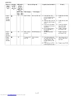
Indoor/
outdoor 
units in 
complete 
shutdown 

2 times

2

-0

Cycle tempera-
ture

Compressor high-
temperature error

(1)

Check the outdoor unit air 
outlet for blockage.

(1)

Ensure unobstructed 
air flow from the out-
door unit air outlet.

(2)

Check if the power supply 
voltage is 90 V or higher at 
full power.

(2)

Connect power sup-
ply of proper voltage.

(3)

Check the pipe connec-
tions for refrigerant leaks.

(3)

Charge the specified 
amount of refrigerant.

(4)

Measure resistance of the 
outdoor unit compressor 
thermistor.
(TH1: Approx. 53 k

Ω

 at 

25

°

C)

(4)

Replace the outdoor 
unit compressor ther-
mistor assembly.

(5)

Check the expansion 
valve for proper operation.

(5)

Replace the expan-
sion valve coil, expan-
sion valve or outdoor 
unit control PWB 
assembly.

Indoor 
unit in 
operation
Outdoor 
unit in 
tempo-
rary stop

-1

Temporary stop due 
to compressor dis-
charge overheat *3

(Temporary stop for cycle pro-
tection)

-2

Temporary stop due 
to outdoor unit heat 
exchanger overheat 
*3

(Temporary stop for cycle pro-
tection)

-3

Temporary stop due 
to outdoor unit heat 
exchanger overheat 
*3

(Temporary stop for cycle pro-
tection)

-4

Temporary stop due 
to 2-way valve 
freeze *3

(Temporary stop for cycle pro-
tection)

Indoor 
unit in 
operation
Outdoor 
unit in 
tempo-
rary stop

3 times

3

-0

Dry operation

Temporary stop due 
to dehumidifying 
operation *3

(Temporary stop for cycle pro-
tection)

Indoor/
outdoor 
units in 
complete 
shutdown

5 times

5

-0

Outdoor unit 
thermistor 
open-circuit

Heat exchanger 
thermistor open-cir-
cuit error

(1)

Check connector CN8 of 
the outdoor unit ther-
mistor for secure installa-
tion.

(1)

Correct the installa-
tion.

-1

Outside tempera-
ture thermistor 
open-circuit error

(2)

Measure resistance of out-
door thermistors TH1 to 
TH5.

(2)

Replace the outdoor 
unit thermistor assem-
bly.

-2

Suction thermistor 
open-circuit error

(3)

Check the lead wires of 
thermistors TH1 through 
TH5 on the outdoor unit 
control PWB for open-cir-
cuit.

(3)

Replace the outdoor 
unit thermistor assem-
bly.

-3

2-way valve ther-
mistor open-circuit 
error

(4)

No abnormality found in 
above inspections (1) 
through (3).

(5)

Replace the outdoor 
unit control PWB 
assembly.

-4

Discharge ther-
mistor open-circuit 
error

Status of 

indoor/

outdoor 

units

Indication 

by LED1 

on out-

door unit 

*2

Malfunction 

No. dis-

played on 

main unit 

display sec-

tion *1

Content of diagnosis

Inspection location/method

Remedy

Main 
cate-

gory

Sub-

cate-

gory

Main category

Sub-category

Summary of Contents for AY-XP12FR

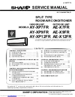
Page 1: ...CONDITION 4 1 3 TEMPERATURE AT EACH PART AND PRESSURE IN 3 WAY VALVE 4 1 4 PERFORMANCE CURVES 4 2 CHAPTER 5 DISASSEMBLING PROCEDURE 1 DISASSEMBLY OF INDOOR UNIT 5 1 2 DISASSEMBLY OF OUTDOOR UNIT 5 7 REPLACEMENT PARTS LIST SERVICE MANUAL AYXP7FR S6512AYXP7FR T SHARP CORPORATION CONTENTS Parts marked with are important for maintaining the safety of the set Be sure to replace these parts with specifi...

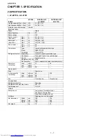
Page 2: ...70cc VG74 Refrigerant system Evaporator Louver Fin and Grooved tube type Condenser Corrugate Fin and Grooved tube type Control Expansion valve Refrigerant R410A 830g De lce system Micro computer controled reversed systems Noise level at cooling High dB A 37 45 Low dB A Soft dB A 28 Fan system Drive Direct drive Air flow quantity at cooling High m3 min 8 0 23 2 Low m3 min 6 8 Soft m3 min 5 5 Fan Cr...

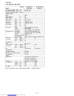
Page 3: ...aporator Louver Fin and Grooved tube type Condenser Corrugate Fin and Grooved tube type Control Expansion valve Refrigerant R410A 830g De lce system Micro computer controled reversed systems Noise level at cooling High dB A 39 45 Low dB A Soft dB A 28 Fan system Drive Direct drive Air flow quantity at cooling High m3 min 8 6 23 3 Low m3 min 7 3 Soft m3 min 5 5 Fan Cross flow fan Propeller fan Conn...

Page 4: ...c RB68A or Freol Alpha 68M Refrigerant system Evaporator Louver Fin and Grooved tube type Condenser Corrugate Fin and Grooved tube type Control Expansion valve Refrigerant R410A 1030g De lce system Micro computer controled reversed systems Noise level at cooling High dB A 40 48 Low dB A Soft dB A 28 Fan system Drive Direct drive Air flow quantity at cooling High m3 min 9 8 26 7 Low m3 min 8 5 Soft...

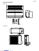
Page 5: ...AYXP7FR 1 4 2 EXTERNAL DIMENSION 1 Indoor unit 2 Outdoor unit 278 198 790 22 0 58 18 5 175 INVERTER AIR CONDITIONER 250 165 167 5 136 81 730 72 540 299 324 515 12 37 5 4 5 58 135 14 ...

Page 6: ...AYXP7FR 1 5 3 WIRING DIAGRM 1 Indooa unit 2 Outdooa unit 2 1 AE X7FR AE X9FR 2 2 AE X12FR 420V 750μF 420V 750μF ...

Page 7: ...to 10 minutes after self diagnosis is performed during operation and the display returns to normal condition after this display period The content of self diagnosis cannot be called out by the self diagnosis display function of the outdoor unit Example of self diagnosis display on outdoor unit Compressor high temperature error c The content of diagnosis is transferred to the indoor unit via serial...

Page 8: ...ion 4 Temporary stop due to 2 way valve freeze 3 Temporary stop for cycle pro tection Indoor unit in operation Outdoor unit in tempo rary stop 3 times 3 0 Dry operation Temporary stop due to dehumidifying operation 3 Temporary stop for cycle pro tection Indoor outdoor units in complete shutdown 5 times 5 0 Outdoor unit thermistor open circuit Heat exchanger thermistor open cir cuit error 1 Check c...

Page 9: ... unit fan motor 3 AC current defi ciency error 1 Check if there is an open circuit in the secondary winding of the current transformer of the outdoor unit control PWB 1 Replace the outdoor unit control PWB assembly 2 Check if the refrigerant volume is abnormally low 2 Charge the specified amount of refrigerant 3 Check if the refrigerant flows properly 3 Correct refrigerant clogs 2 way valve 3 way ...

Page 10: ...er supply 2 No abnormality found in above inspection 1 2 Replace the outdoor unit control PWB assembly Indoor outdoor units in operation 1 PAM clock error 1 Check the PAM clock for proper input 1 Replace the outdoor unit control PWB assembly Indoor unit in operation Outdoor unit in complete shutdown 17 0 Wires between units Serial open circuit 1 Check the wires between units 1 Connect stable power...

Page 11: ... control PWB Indoor outdoor units in operation 20 0 Indoor unit con trol PCB EEPROM data error EEPROM read data error Replace the indoor unit control PWB Indoor outdoor units in operation 88 Control and dis play PCB Communication error 1 Check for disconnected connector between control PCB and display PCB and open circuit in lead wires 1 Insert connectors cor rectly or replace con trol PWB 2 Check...

Page 12: ...alfunction code is called out 3 Indoor unit relay Malfunction diagnosis display Relays turns Off after about 30 minutes None Displays 18 0 when malfunction code is called out 4 Indoor unit relay Malfunction diagnosis display Turns On momentarily then turns Off 18 1 5 Indoor unit relay Malfunction diagnosis display Turns On momentarily then turns Off 18 1 Indoor unit Outdoor unit 1 N 2 1 N 2 Indoor...

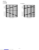
Page 13: ...ng 1 2 At Heating 2 AY XP9FR 2 1 At Cooling 2 2 At Heating 25 30 35 40 2 0 2 2 2 4 2 6 300 400 500 600 Cooling capacity kW Outside air temp ºC Input W 5 0 7 5 10 1 5 2 0 2 5 3 0 500 600 400 Heating capacity kW Outside air temp ºC Input W 25 30 35 40 2 4 2 6 2 8 3 0 3 2 900 600 700 800 Cooling capacity kW Outside air temp ºC Input W 5 0 5 7 10 3 0 2 5 3 5 2 0 700 800 600 Heating capacity kW Outside...

Page 14: ...1 At Cooling 3 2 At Heating 25 30 35 40 3 2 3 4 3 6 3 8 4 0 1200 900 1000 1100 Cooling capacity kW Outside air temp ºC Input W 5 0 5 7 10 3 5 4 0 4 5 3 0 2 5 1000 1100 1200 900 800 Heating capacity kW Outside air temp ºC Input W ...

Reviews: