background image

PLASMACLUSTER UNIT


SERVICE MANUAL

AY-XPC12PU

SB211AYXPC2PU/T

Parts marked with "

" are important for maintaining the safety of the set. Be sure to replace these parts with specified ones for maintaining the

safety and performance of the set.

This document has been published to be used for
after sales service only.
The contents are subject to change without notice.

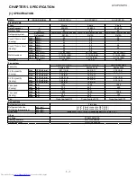
CHAPTER 1. PRODUCT SPECIFICATIONS

[1] SPECIFICATION............................................ 1-1
[2] EXTERNAL 

DIMENTIONS............................. 1-2

[3] ELECTRICAL 

PARTS .................................... 1-3

[4] WIRING 

DIAGRAMS...................................... 1-3

CHAPTER 2. EXPLANATION OF CIRCUIT AND 
OPERATION

[1] BLOCK 

DIAGRAMS....................................... 2-1

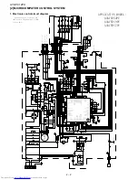
[2]  MICROCOMPUTER CONTROL SYSTEM ........... 2-2
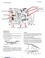
[3] FUNCTION..................................................... 2-3
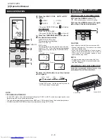
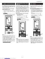
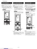
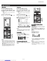
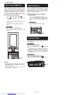
[4] OPERATION 

MANUAL .................................. 2-6

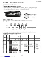
CHAPTER 3. TROUBLE SHOOTING GUIDE

[1] SELF-DIAGNOSIS 

FUNCTION .....................3-1
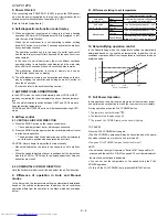
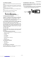
[2] THERMISTOR 

TEMPERATURE 

CHAR-

ACTERISTICS...............................................3-8

.................................

....

3-8
3-9

CHAPTER 4. DISASSEMBLING PROCEDURE

[1] INDOOR 

UNIT

INDOOR UNIT

...............................................4-1

CHAPTER 5. INSTALLATION INSTRUCTION

[1] .............................................5-1

[2] ..............................4-4

Parts Guide

TopPage

CONTENTS

MODEL

In the interests of user-safety (Required by safety regulations in some countries)  the set should
be restored to its original condition and only parts identical to those specified should be used.

AY-XPC07PU
AY-XPC09PU
AY-XPC12PU

[3]  AIR CONDITIONER OPERATION IN 

THERMISTOR ERROR

[4]  GENERAL TROUBLESHOOTING CHART

SPLIT TYPE

ROOM AIR CONDITIONER

(INDOOR UNIT)

Summary of Contents for AY-XPC07PU

Page 1: ...ND OPERATION 1 BLOCK DIAGRAMS 2 1 2 MICROCOMPUTER CONTROL SYSTEM 2 2 3 FUNCTION 2 3 4 OPERATION MANUAL 2 6 CHAPTER 3 TROUBLE SHOOTING GUIDE 1 SELF DIAGNOSIS FUNCTION 3 1 2 THERMISTOR TEMPERATURE CHAR ACTERISTICS 3 8 3 8 3 9 CHAPTER 4 DISASSEMBLING PROCEDURE 1 INDOOR UNIT INDOOR UNIT 4 1 CHAPTER 5 INSTALLATION INSTRUCTION 1 5 1 2 4 4 Parts Guide TopPage CONTENTS MODEL In the interests of user safet...

Page 2: ...L Cluster generator Rmote controller Refrigerant system Sound Presure Level Cooling Sound Presure Level Heating Net dimensions Fan motor Air flow quantity Cooling Refrigerant tube size A Gas line B Liquid line Fan speed Heating Fan Air filters 38 26 28 36 7 32 920 11 13 32 290 22 10 CMOT A562JBKZ 8poles 30W Cross flow fan Φ110 9 7 16 240 AY XPC07PU Single 208 230 60 Louver fin and Grooved tube typ...

Page 3: ...ION Indoor unit AY XPC12PU s k r a m e R l e d o M e m a N t r a P Fan motor Louver motor 1 u F 02725 027 6 9 9 5027 3 ELECTRICAL PARTS 4 WIRING DIAGRM 36 2 920 9 4 240 11 4 290 Remote controller 0 7 18 8 0 204 2 2 57 4 6 9 ...

Page 4: ...t circuit Heat exchanger temp thermistor Liquid pipe VALVE detect circuit Liquid pipe temp thermistor 2 1 AHXPC12LV 5GTXKEG CPWCN CHAPTER 2 EXPLAMATION OF CIRCUIT AND OPERATION 1 BLOCK DIAGRAMS AY XPC12PU Switching transformer ...

Page 5: ...5 3 7 62 3 62 7 3 6 5 3 6 6 3 3 3 1 3 1 3 1 3 1 3 1 3 1 3 1 95 0 3 1 95 3 3 3 6 6 3 6 5 6 3 62 7 1 3 72 3 7 3 173 3 173 33 3 3 9 S 9 X N 5 N 5 N 5 9 X 9 N 5 1 5 N 1 5 N 5 N 5 5 N N 5 N 5 5 5 5 5 N 5 N 5 6 7 3 3 7 03 ć 52 1 8 5 N 5 1 N 5 5 6 9 3 0 3 6 6 9 9 3 3 3 9 1 1 N 5 5 N 5 N 7 4 51 5 N 9 X 5 N 3 5 5 5 S 9 S 9 9 S 1 9 7 5 722 5 6 7 0 1 5 N 5 5 N 5 N 9 9 9 9 9 9 9 9 9 9 9 9 9 9 9 9 9 9 9 9 9 1 ...

Page 6: ...justed based on fuzzy logic calculations 1 hour before the set time so that the room temperature reaches the set temperature at the set time AY XPC12PU 4 OFF Timer Sleep Operation The OFF timer can be activated by pressing the OFF timer button When the OFF timer is set the operation stops after the set time When this timer is set the compressor operating frequency lowers for quieter operation and ...

Page 7: ...ion control In the Dehumidifying mode the temperature setting is automatically determined based on the outside air temperature In addition the air conditioner operation differs from the operation in the Manual mode as explained below 11 Full Power Operation 27ºC 0 0 5 1 0 1 5 25ºC 25ºC 28ºC 22ºC 22ºC Room Temperature Preset temperature In the AUTO mode the unit will automatically select COOL or HE...

Page 8: ...matic operation Temperature setting Fan setting Air flow direction Power ON OFF Automatic operation mode setting Swing louver Plasmacluster mode 14 2 Setting not memorized Timer setting Full power setting Self cleaning 14 3 Disabling auto restart function By removing cutting jumper JP on the printed circuit board PCB the auto restart function can be disabled 15 Explanation of cluster circuit The c...

Page 9: ...TIPS ABOUT AUTO MODE n e AUTO mode e unit will automatically select COOL or HEAT mode by comparing e room temperature and your desired temperature e unit will automatically switc between HEAT and COOL mode to keep e desired temperature COANDA and MULTI SPACE button will be inactivated during AUTO mode VERTICAL AIR FLOW DIRECTION 1 Press the SWING button e vertical louver will swing 2 Press the SWI...

Page 10: ...et obliquely upward to de liver cool air to the ceiling in order to avoid direct 1 During operation press the COAN DA AIFLOW button HEAT mode The remote control will display COOL DRY mode The remote control will display TO CANCEL Press the COANDA AIFLOW button again NOTE If you want COANDA AIRFLOW operation in FULL POWER mode press COANDA AIR FLOW button during FULL POWER operation The COANDA AIRF...

Page 11: ...d AUTO op eration press the SILENT button The speed icon on the remote control will display SILENT TO CANCEL Press the SILENT button again 1 FULL POWER OPERATION SILENT OPERATION 1 When the 1 2 3 5h OFF TIMER is set the unit will automatically turn off after the set ting hours 1Press the 1 2 3 5h OFF TIMER but ton to set the desired time The orange TIMER lamp will light up The remaining time will ...

Page 12: ... set the desired time The time can be set in 10 minute incre ments 3Press the SET C button The orange TIMER lamp will light up 4Select the mode temperature and fan speed as desired Press below buttons to select mode HEAT COOL AUTO DRY Press the TEMPERATURE button or to set the desired temperature Press the FAN button to set the desired fan speed CANCEL TO CHANGE TIME SETTING Cancel the TIMER setti...

Page 13: ... eliminated by this operation SELF CLEAN OPERATION 1 Press the DISPLAY button when the lamps on the unit are too bright The green OP ERATION lamp and the orange TIMER lamp cannot be turned off 1During operation press the DIS PLAY button The blue PLASMACLUSTER lamp 5 F 15 C AUTO OFF lamp and or the green FULL POWER lamp will turn off TO LIGHT UP Press the DISPLAY button again DISPLAY BUTTON 1 Use t...

Page 14: ...cation in order to get a correct conclusion LED1 Ma f o Normal condition Normal blinking O O O O O Timer Orange 0 0 Normal Operation Green Plasmacluster Blue Indoor and outdoor units do not oper ate 1 time O O O O O Timer Orange 1 0 Outdoor unit thermistor short circuit Heat exchanger thermistor short circuit error 1 Measure the resistance of the outdoor unit thermistors 2 Check the lead wire of t...

Page 15: ...gh temperature error Replace the outdoor unit control PCB assembly O Operation Green O O Plasmacluster Blue Plasmacluster Blue AY XPC12PU _ Q Q Q Indoor unit operates Outdoor unit does not operate temporarily 3 time Timer Orange tion Temporary stop due to dehumidi fying operation Temporary stop for cycle protection Operation Green 3 0 Dry opera Heat operation 5 15 AUTO OFF Measure the resistance o...

Page 16: ...s Stop valve pipe expansion valve O O O Operation Green O O Plasmacluster Blue Indoor and outdoor units do not operate 8 time O O O O O Timer Orange 8 0 0 Abnormal wire check Abnormal wire check error 1 Check the expansion valve 2 Are four expansion valves connected by mistake 3 Check the wiring between units 1 Replace the outdoor control board assembly 2 Reattach 3 Check the wiring between units ...

Page 17: ...ntrol PWB assembly O O O Operation Green O Plasmacluster Blue O O O O O Timer Orange 5 Outdoor unit DC fan open connector error 1 Check connector CN3 of the outdoor unit DC fan motor for secure installation 2 No abnormality found in above inspection 1 1 Correct the installa tion 2 Replace the outdoor unit control PWB assembly O O O Operation Green O O Plasmacluster Blue Indoor and outdoor units do...

Page 18: ... PCB 1 Connect stable power supply Correct the wiring 2 Replace the outdoor unit control PWB assembly 3 Replace the fuse outdoor unit control PWB assembly 4 Replace the outdoor unit control PWB assembly 5 Replace the outdoor unit fan motor 6 Replace the outdoor unit control PWB O O Operation Green Plasmacluster Blue Indoor unit operates Outdoor unit does not operate Lighting or OFF O O O O O Timer...

Page 19: ...hermistor 1 Check connector of thermistor for secure installation 1 Replace the ther mistor 2 Check the tempera ture properties of the thermistor 2 Replace the ther mistor Problem symptom Outdoor unit indi cation LED1 Indoor unit Malfunc tion No Content of diagnosis Check point Action Lamp Main Sub Main Sub o Remark The malfunction No is calculated using the following way Example Indoor unit lamp ...

Page 20: ...s securely Modify or replace termistor Are stop valves liquid and gas close Does compressor rotate Check IPM lead wire Check short circuit Check compressor terminal Does compressor rotate Does compressor rotate more than 30 seconds Is IPM PWB floating from the heat sink Check the AC power supply voltage when compressor rotate rated voltage 10 Cooling mode Check indoor heat exchanger termistor and ...

Page 21: ...oom temperature is low Cooling mode is acti vated in most cases Heating mode is activated even if room temperature is high Heating mode is always activated Cooling Frequency control Room becomes too cold Air conditioner oper ates in full power even when set tem perature is reached Room does not become cool Compressor does not operate Dehumidifying Room temperature memory Frequency control Normal o...

Page 22: ...urn off light and check Signal should be received when light is turned off Change light position or install new fluorescent lamp Use Sevick light Hitachi Check if Sevick light Hitachi is used Signal may not be received sometimes due to effect of Sevick light Replace light or change position Operating position angle is inap propriate Operate within range specified in manual Signal should be receive...

Page 23: ...terminal board Pay attention to the three hooks 2 Open open panel reverse it and remove it by the direction shown in the picture 3 Remove the screw fixing cord holder and then remove it 1 Remove power cord from OUTDOOR UNIT and remove Unit to Unit wire connected with the board 5 Slide out 2 air filters Hook ...

Page 24: ...e underside catch then push the upper hooks and remove 8 Loosen the 2 screws push the hook filter guide and remove front panel L 7 Loosen the screw push the hook 9 Remove thermistor wire and loosen the screw fixing earth wire ...

Page 25: ...0 Lift the hook reverse control box and pull it toward in the direction 11 Remove 3 connectors and cut 2 12 Lift the upper hook and remove control box ass y 13 Loosen 2 screws take off drain pan shown in the picture cover HOOK HOOK ...

Page 26: ...cross flow fan and then separate cross flow fan 16 Loosen 3 screws and remoce evaporator ass y fan motor insert the motor shaft in the boss of cross flow fan to the ring position shown in the picture When assembling cross flow fan and and fan motor 17 Cut the fixing band and remove side cover L ...

Page 27: ...oosen 2 screws and remove LED holder side cover R 20 Push the hook and reverse 22 Lift the hook and remove LED PWB Hook 23 Remove the center shaft of horizontal louver from louver holder with lifting the louver holder and remove the left shaft of while warping horizontal louver from drain pan and take terminal board up ...

Page 28: ...w and remove louver motor 24 Loose 1 screws of guard holder for wire guard and then take off guard holder Unhook the wire guard as shown below and then take off wire guard Same as left side plasmacluster ass y and remove plasmacluster unit 27 Push 3 hooks open Hook 26 Cut the fixing band and remove plasmacluster ass y Hook ...

Page 29: ... the room if refrigerant gas leaks during installation If the refrigerant gas contact with re it will generate toxic gas Use the speci ed electrical cable Make sure the cable is secured in place and that the terminals are free of any excess force from the cable Otherwise overheating or re may result Form the cable so that the control box cover the cord holder and cable holder are not loose Otherwi...

Page 30: ... cable for the indoor side 2 T f 3 T ff the Connection Holder from the Wire Conduit and attach the Con _ r 5 Attach the Cable Holder and Connection Holder to Cabinet with screw Refer to ATTACH THE CABLE HOLDER AND CONNECTION HOLDER Fig 3 6 7 Open the Open Panel 8 Connect the Connecting Cable to Terminal Board Fig 1 9 Fix the Cacle cover with the screw 10 Tighten the Connection Holder to Wire Condu...

Page 31: ...d apply the bottom hooks to the mounting plate s support 5 in place For left side piping 1 Reverse the positions of the drain hose and drain cap Refer to Exchange the drain hose 2 Connect the pipes and wrap tape around the insulation of the piping joints tightly not to become thick 3 Pass the pipes connecting cable and the drain hose through the piping hole 4 Hook the unit onto the mounting plate ...

Page 32: ...e unit for over 5 seconds until a beep sound is heard and an operation 3 Make sure the system runs well To stop the operation press the AUX button again 8 ITEMS TO CHECK Is the earth wire connected properly arranged Is the drainage properly Is there any gas leakage at the pipe connection 5 F 15 C AUTO OFF function will be used or not EXPLANATION TO CUSTOMER Ask the customer to carefully read the o...

Page 33: ...hout notice AY XPC12PU AY XPC07PU AY XPC09PU AY XPC12PU HOW TO ORDER REPLACEMEN Parts of AY XPC07PU and AY XPC09PU are still under revision may change for reliability improvement New edition of this manual will be issued after revision is completed T PARTS To have your order filled promptly and correctly please furnish the following information 1 MODEL NUMBER 2 REF NO 3 PART NO 4 DESCRIPTION Parts...

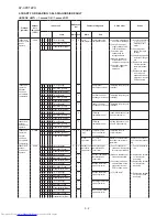
Page 34: ...AY XPC12PU 2 1 INDOOR UNIT PARTS ...

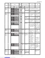
Page 35: ...AY XPC12PU 3 ...

Page 36: ...4 AY XPC12PU ...

Page 37: ...ZZ N THERMISTOR 4 12 PCOV C009JBWZ N TERMINAL COVER 4 13 PCOV C008JBFA N SW COVER 4 14 LHLD B234JBFA N HOLDER 4 15 LHLD B235JBFA N CORD HOLDER 4 16 FSGY B717JBKZ N DISPLAY BOARD UNIT 5 1 LPLT A058JBPZ HOSE HOLDER 5 2 PHOS A052JBEZ DRAIN HOSE 5 3 1 CKITTA159AKKZ PLASMACLUSTER UNIT 5 3 2 LHLD B214JBFA N CLUSTER HOLDER 5 3 3 PCOV C005JBFA N CLUSTER COVER 5 3 4 QW VZG741JBZZ LEAD WIRE 5 4 DSRA A406JBK...

Page 38: ...8 PFILMA283JBEA N AIR FILTER 7 9 PGID A203JBFA N FILTER GUIDE 7 10 PPLTNA143JBWZ MOUNTING ANGLE 7 11 TSPC H659JBRA N NAME LABEL AY XPC12PU 7 11 TSPC H693JBRA N NAME LABEL AY XPC9PU 7 11 TSPC H777JBRA N NAME LABEL AY XPC7PU 2 ACCESSORY PARTS 1 1 CRMC A868JBEZ REMOTE CONTROL 1 2 LHLD A484JBFA HOLDER 1 3 DHLD A073JBKZ N CORD HOLDER ASSY 1 4 FFZK A256JBKZ SCREWS KIT 1 5 UBATUA027JBE0 BATTERY PACK 1 7 ...

Reviews: