13
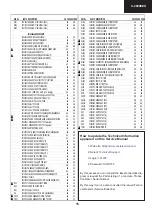
AK - 45
CHASSIS
- -
- 64
- NC
LV
Not
connected
- -
- 63
- NC
LV
Not
connected
27 56 45 62 48 AVSS
X
Analog
ground
- -
- 61
- AVSS
X
Analog
ground
28 55 44 60 47 MONO_IN IN LV
Mono
input
- -
- 59
- NC
LV
Not
connected
29 54 43 58 46 VREFTOP
X
Reference voltage IF A/D
converter
30 53 42 57 45 SC1_IN_R IN LV
SCART
1
input,
right
31
52
41
56
44
SC1_IN_L
IN
LV
SCART 1 input, left
32
51
-
55
43
ASG1
AHVSS
Analog Shield Ground 1
33 50 40 54 42 SC2_IN_R IN LV
SCART
2
input,
right
34
49
39
53
41
SC2_IN_L
IN
LV
SCART 2 input, left
35
48
-
52
40
ASG2
AHVSS
Analog Shield Ground 2
36 47 38 51 39 SC3_IN_R IN LV
SCART
3
input,
right
37
46
37
50
38
SC3_IN_L
IN
LV
SCART 3 input, left
38
45
-
49
37
ASG4
AHVSS
Analog Shield Ground 4
39 44 -
48 36 SC4_IN_R IN LV
SCART
4
input,
right
40
43
-
47
35
SC4_IN_L
IN
LV
SCART 4 input, left
41
-
-
46
-
NC
LV or AHVSS
Not connected
42 42 36 45 34 AGNDC
X
Analog
reference
voltage
43 41 35 44 33 AHVSS
X
Analog
ground
- -
- 43
- AHVSS X
Analog
ground
- -
- 42
- NC
LV
Not
connected
- -
- 41
- NC
LV
Not
connected
44 40 34 40 32 CAPL_M
X
Volume
capacitor
MAIN
45
39
33
39
31
AHVSUP
X
Analog power supply 8V
46 38 32 38 30 CAPL_A
X
Volume
capacitor
AUX
47
37
31
37
29
SC1_OUT_L
OUT
LV
SCART output 1, left
48
36
30
36
28
SC1_OUT_R
OUT
LV
SCART output 1, right
49 35 29 35 27 VREF1
X
Reference
ground
1
50
34
28
34
26
SC2_OUT_L
OUT
LV
SCART output 2, left
51
33
27
33
25
SC2_OUT_R
OUT
LV
SCART output 2, right
52
-
- 32
- NC
LV
Not
connected
53 32 -
31 24 NC
LV
Not
connected
54 31 26 30 23 DACM_SUB
OUT LV
Subwoofer
output
55 30 -
29 22 NC
LV
Not
connected
56 29 25 28 21 DACM_L
OUT LV
Loudspeaker
out,
left
57 28 24 27 20 DACM_R OUT LV
Loudspeaker
out,
right
58 27 23 26 19 VREF2
X
Reference
ground
2
59 26 22 25 18 DACA_L
OUT LV
Headphone
out,
left
60 25 21 24 17 DACA_R
OUT LV
Headphone
out,
right
- -
- 23
- NC
LV
Not
connected
- -
- 22
- NC
LV
Not
connected
61 24 20 21 16 RESETQ
IN X
Power-on-reset
62 23 -
20 15 NC
LV
Not
connected
63 22 -
19 14 NC
LV
Not
connected
64 21 19 18 13 NC
LV
Not
connected
65 20 18 17 12 I2S_DA_IN2
IN LV
I
2
S2-data input
66 19 17 16 11 DVSS
X
Digital
ground
- -
- 15
- DVSS
X
Digital
ground
- -
- 14
- DVSS
X
Digital
ground
67 18 16 13 10 DVSUP
X
Digital
power
supply
5V
- -
- 12
- DVSUP X
Digital
power
supply
5V
- -
- 11
- DVSUP X
Digital
power
supply
5V
68 17 15 10 9
ADR_CL
OUT LV
ADR
clock
13.4.VDP313xY
13.4.1.Introduction
The VDP 313xY is a video IC family of high-quality single-chip video processors. Modular design and a
sub-micron technology allow the economic integration of features in all classes of TV sets. The VDP
313xY family is based on the VDP 31xxB including YC
R
C
B
inputs for DVD component signals.
The VDP 313xY includes complete video, display and deflection processing. All processing is done
digitally, the video front-end and video backend are interfacing to the analog world. Most functions of
the VDP can be controlled by software via I
2
C-Bus interface
Summary of Contents for C-2890EES
Page 7: ...7 C 2890EES CHASSIS LAYOUT Mother Unit CRT Unit Control Panel Unit ...
Page 69: ...53 AK 45 CHASSIS 14 6 GEOMETRY ADJUSTMENT 4 3 FORMATS 4 3 MODE 16 9 MODE ...
Page 70: ...54 AK 45 CHASSIS 16 9 FORMATS AUTO MODE ...
Page 71: ...55 AK 45 CHASSIS REGULAR MODE ...
Page 72: ...56 AK 45 CHASSIS ZOOM 14 9 MODE ...
Page 73: ...57 AK 45 CHASSIS ZOOM 16 9 MODE ...
Page 74: ...58 AK 45 CHASSIS SUBTITLE ZOOM MODE ...
Page 75: ...59 AK 45 CHASSIS FULL MODE ...
Page 76: ...60 AK 45 CHASSIS PANORAMIC MODE ...
Page 86: ...70 AK 45 CHASSIS 1 I H G F E D C B A 2 3 4 5 6 7 16 7 Schematic Diagram of CRT Socket Circuit ...
Page 91: ...75 AK 45 CHASSIS Notes ...

