background image

R-1874

SUPPLEMENTAL SERVICE MANUAL

TABLE OF CONTENTS

Page

PRECAUTIONS TO BE OBSERVED BEFORE AND DURING SERVICE TO
AVOID POSSIBLE  EXPOSURE TO EXCESSIVE MICROWAVE ENERGY ................... INSIDE FRONT COVER
BEFORE SERVICING ...................................................................................................... INSIDE FRONT COVER
MICROWAVE MEASUREMENT PROCEDURE ..................................................................................................... 1
WARNING TO SERVICE PERSONNEL..........................................................................................................3
FOREWORD .......................................................................................................................................................... 4
PRODUCT SPECIFICATIONS ............................................................................................................................... 5
GENERAL  INFORMATION ................................................................................................................................... 5
PICTORIAL DIAGRAM .......................................................................................................................................... 7
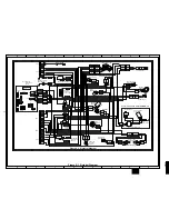
CONTROL PANEL CIRCUIT .................................................................................................................................. 8
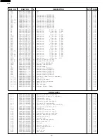
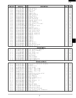
PARTS LIST .......................................................................................................................................................... 9
PACKING AND ACCESSORIES ......................................................................................................................... 15

SHARP ELECTRONICS CORPORATION

This document has been published to be used for after sales service only. The contents are subject to change without notice

.

Service Headquarters: Sharp Plaza, Mahwah, New Jersey, 07430-2135

OR:

SHARP CORPORATION

SHARP ELECTRONICS OF CANADA LTD.

Head Office: 335 Britannia Road East, Mississauga, Ontario L4Z 1W9

(905) 890-2100

This is a supplemental Service Manual for Model R-1874.
This model is quite similar to Base Model R-1855A (S/M# S01M177R1875E).
Use this supplemental manual together with the Base Model Service Manual for complete operation and service information

In the interest of user-safety, the oven should be restored to its original condition and only parts identical to those specified
should be used.

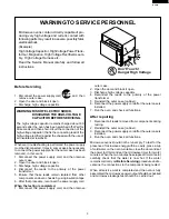
WARNING TO SERVICE PERSONNEL: Microwave ovens contain circuitry capable of producing very high voltage and
current, contact with following parts may result in a severe, possibly fatal, electrical shock. (High Voltage Capacitor, High
Voltage Power Transformer, Magnetron, High Voltage Rectifier Assembly,  High Voltage Harness etc..)

S52M187R1874E

OVER THE RANGE

MICROWAVE OVEN

   MODEL

  R-1874

(IN USA):

(IN CANADA):

MIX CONV

DEFROST

SENSOR

TURNTABLE ON OFF COOK LBS OZ KG HELP

Summary of Contents for Carousel R-1874

Page 1: ...e 335 Britannia Road East Mississauga Ontario L4Z 1W9 905 890 2100 This is a supplemental Service Manual for Model R 1874 This model is quite similar to Base Model R 1855A S M S01M177R1875E Use this supplemental manual together with the Base Model Service Manual for complete operation and service information In the interest of user safety the oven should be restored to its original condition and o...

Page 2: ...e unit perform a microwave emission check as per the Microwave Measurement Procedure outlined in this service manual If microwave emissions level is in excess of the specified limit contact SHARP ELECTRONICS OF CANADA LTD immediately If the unit operates with the door open service person should 1 tell the user not to operate the oven and 2 contact SHARP ELECTRONICS OF CANADA LTD and NHW CANADA imm...

Page 3: ...center of the oven cavity The water container shall be a low form of 600 ml 20 oz beaker with an inside diameter of approx 8 5 cm 3 1 2 in and made of an electrically nonconductive material such as glass or plastic Theplacingofthisstandardloadintheovenisimportantnotonlytoprotecttheoven butalsotoinsurethatanyleakage is measured accurately 4 Set the cooking control on Full Power Cooking Mode 5 Close...

Page 4: ...etthecookingcontrolonFullPowerCookingMode Closethedoorandselectacookcycleofseveralminutes Ifthewater begins to boil before the survey is completed replace it with 275 ml of cool water C Leakage test with enclosure installed 1 Grasp the probe of the survey instrument and hold it perpendicular to the gap between the door and the body of the oven 2 Move the probe slowly not faster than 2 5 cm sec alo...

Page 5: ...4 Disconnect the leads to the primary of the power transformer 5 Ensure that these leads remain isolated from other components and oven chassis by using insulation tape 6 After that procedure reconnect the power supply cord When the testing is completed 1 Disconnect the power supply cord and then remove outer case 2 Open the door and block it open 3 Discharge high voltage capacitor 4 Reconnect the...

Page 6: ...sed B The door brackets and hinges are not defective C The door packing is not damaged D The door is not deformed or warped E There is no other visible damage with the oven Servicing and repair work must be carried out only by trained service personnel DANGER Certain initial parts are intentionally not grounded and present ariskofelectricalshockonlyduringservicing Serviceperson nel Do not contact ...

Page 7: ...r P 10 approx 10 of Full Powe P 0 No power throughout the cooking time CUSTOM HELP pad SENSOR COOK pad COMPU BROIL pad COMPU ROAST pad COMPU BAKE pad SENSOR REHEAT pad MINUTE PLUS pad POPCORN pad COMPU DEFROST pad CONVECTION pad REHEAT pad LOW MIX BAKE pad HIGH MIX ROAST pad BROIL pad SLOW COOK pad KITCHEN TIMER pad Number and temperature selection pads CLOCK pad KEEP WARM pad TURNTABLE ON OFF pad...

Page 8: ...through window 2 Door hinges 3 Stirrer cover 4 Turntable motor shaft 5 Oven lamp It will light when oven is operating or door is open 6 Door latches The oven will not operate unless the door is securely closed 7 One touch door open button Push to open door 8 Auto Touch control panel 9 Ventilation openings 10 Light Cover 11 Grease filters 12 Removable turntable The turntable will rotate clockwise o...

Page 9: ...Blue Marking Blue Marking OVEN LAMP SOCKET to oven cavity front flange CN E CN F 1 2 YLW GRY CN A 5 4 RED GRY WHT WHT BLK BLK SECONDARY INTERLOCK SWITCH N O N C COM COM MONITOR SWITCH MONITOR FUSE AND FUSE HOLDER N O N O COM COM GRN GRN PNK N O COM DOOR SENSING SWITCH CN C CN E CN F CN A PRIMARY INTERLOCK RELAY RY3 RY1 RY9 RY7 CN F T1 1 2 RED WHT 3 AH SENSOR HOOD FAN MOTOR STIRRER MOTOR GRY BLK BL...

Page 10: ...T 1 VR E F AN7 AN6 AN5 AN4 AN3 AN2 AN1 AN0 P55 P30 P31 P32 P33 P34 P35 P36 P37 P00 P01 P02 P03 P04 P05 P06 P07 P10 P11 P12 P13 P14 P15 P16 P17 P20 P21 P22 P23 P24 P25 P26 P27 P54 P53 P52 P51 P50 P47 P46 P45 P44 P43 P42 P40 P71 P70 XIN XOUT VS S R S T INT1 VCC VE E AVS S 12 A A B C B C C 4 10µ 35v C 12 10µ 35v C65 100µ 16v C 20 10µ 35v R 30 15k R 50 15k R 63 220F R 64 3 6 kF R 31 4 7k R 62 36kF R 5...

Page 11: ...chematic diagram 1 AB 2 7 FANGKB009MRY0 M Hood lamp glass assembly 1 AM 2 7 1 LANGQB016MRP0 M Hood lamp glass angle 1 AG 2 7 2 PGLSPB004MRE0 M Hood lamp glass 1 AH 2 8 PCOVPB030MRT0A M Base cover 1 AX 2 9 FDECAB028MRK0 M Sash left 1 AL 2 10 LSTY B010MRP0 M Rear stay 1 AG CONTROLPANELPARTS 3 1 DPWBFB061MRU0 M Control unit 1 BQ 3 1A QCNCMA227DRE0 J 3 pin connector CN A 1 AC 3 1B QCNCMA230DRE0 J 4 pi...

Page 12: ...124LM 6 AG RY10 RRLY B001MRE0 M Relay VE 24HSF K 1 AM SP40 RALM A014DRE0 J Buzzer PKM22EPT 1 AG T1 RTRNPB004MRE0 M Transformer 1 AN VRS1 RH VZA032DRE0 J Varistor 10G471K 1 AE ZD1 VHEHZ6A3 1 J Zener diode HZ6A 3 1 AC ZD2 VHEHZ161 1 J Zener diode HZ16 1 1 AA ZD3 VHEHZ5C2 1 J Zener diode HZ5C 2 1 AA ZD4 VHEHZ4A2 1 J Zener diode HZ4A 2 1 AA 3 2 FPNLCB407MRK0 M Control panel sub assembly 1 BB 3 2 1 FUN...

Page 13: ...ise filter angle 1 AE 4 56 PDUC B122MRP0 M Exhaust duct B 1 AD DOORPARTS 5 1 CDORFB312MRK0 M Door assembly complete 1 BM 5 2 DDORFB074MRY0 M Door panel assembly 1 BB 5 3 FCOV B216MRK0 M Door frame 1 AT 5 4 PGLSPB047MRR0 M Door glass front 1 AR 5 5 GCOVHB031MRF0 M Choke cover 1 AM 5 6 LSTPPB025MRF0 M Latch head 1 AE 5 7 LSTPPB037MRF0 M Glass stopper 2 AC 5 8 MSPRTA046WRE0 M Latch spring 1 AB 5 9 XC...

Page 14: ...ng 1 AA 7 16 XOTSD40P12000 M Screw 4mm x 12mm 2 AC 7 17 XCTWW40P08000 M Screw 4mm x 8mm 1 AA 7 18 LX NZA002WRE0 M Nut 4mm x 3 2mm 1 AB 7 19 XWSUW40 10000 M Spring Washer 1 AA 7 20 LX BZA041WRE0 M Screw 4mm x 8mm 9 AA 7 21 XWHSD50 20120 M Washer 5mm x 2mm 1 AA 7 22 XWHUW40 08100 M Washer 4mm x 0 8mm 2 AA 7 23 XWHUW50 08120 M Washer 5mm x 0 8mm 1 AA 7 24 XOTSD40P08000 M Screw 4mm x 8mm 9 AA 7 25 XOT...

Page 15: ...2 4 26 1 11 1 11 4 34 4 43 4 13 7 25 4 9 4 12 6 12 7 18 4 14 4 19 4 17 7 6 4 13 4 8 1 4 7 22 7 22 1 9 1 2 4 4 4 31 4 48 4 29 4 28 4 47 2 8 1 20 4 33 7 19 7 12 7 12 1 20 1 8 1 11 7 5 4 27 7 16 2 1 2 1 7 10 7 10 4 42 1 5 7 20 7 1 1 19 7 9 4 50 4 21 4 23 1 1 4 41 4 15 7 13 1 7 4 5 4 6 2 2 4 3 4 2 7 25 7 8 2 7 2 2 7 1 7 2 4 7 1 15 1 3 4 22 7 24 7 11 7 11 6 13 7 24 7 7 7 25 2 10 7 7 7 7 7 7 7 7 7 20 7 ...

Page 16: ...1 2 3 6 4 5 1 2 3 A B C D E F G H A B C D E F G H 6 6 6 8 6 9 6 10 6 11 6 1 6 1 1 6 1 2 6 1 3 6 1 7 6 1 5 6 1 6 6 1 4 5 3 4 35 5 4 5 6 5 5 5 7 5 2 5 1 5 9 5 8 3 2 3 3 7 7 3 3 3 1 3 2 3 3 2 1 3 2 4 3 2 5 6 15 3 2 2 5 10 ...

Page 17: ... INSTALL MATERIAL ASSEMBLY 6 1 COOK BOOK 6 7 6 2 LOW RACK 6 10 6 3 OPERATION MANUAL WALL TEMPLATE INSTALLATION INSTRUCTION 6 4 TOP TEMPLATE 6 5 4 3 TURNTABLE TRAY 4 1 DAMPER ASSEMBLY 4 2 TURNTABLE SUPPORT ASSEMBLY MILLER MAT TOP PAD DOOR PROTECTOR BOTTOM PAD PACKING CASE WRAP COVER Non replaceable items HIGH RACK 6 9 TAPE ...

Page 18: ...16 R 1874 NOTES ...

Page 19: ...17 R 1874 NOTES ...

Page 20: ...02BYSHARPCORPORATION ALL RIGHTS RESERVED Nopartofthispublicationmaybereproduced stored in retrieval systems or transmitted in any form or by any means electronic me chanical photocopying recording or other wise without prior written permission of the publisher ...

Reviews: