


CD-BA160H/1700H
– 22 –
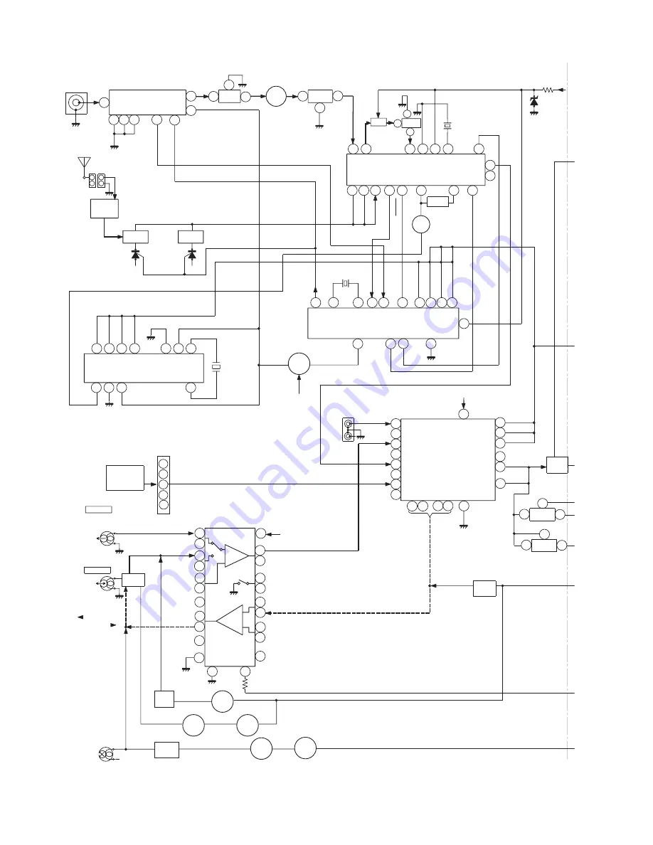
Figure 22 BLOCK DIAGRAM (2/3)
AM LOOP
ANTENNA
XIN
VDDD
VSSD
DO
CL
DI
CE
XOUT
VDDA
VSSA
IN
MPX
FM AFC
BALUN
REC/PLA
CL
CE
DI
SYSTEM
MUTE
DO
CL
DI
CE
MO/ST
+B1
SWITCHING
+B1
FM/AM
OUT
FM/AM
+B
L-CH
R-CH
BAIS
T1/T2
MUTING
PLAYBACK
RECORD
AC BIAS
R-CH
L-CH
CD R
TAPE R
AUX L
TAPE L
TUNER L
CD L
PB
FROM CD
SECTION
ERASE
HEAD
SWITCHING
SWITCHING
SWITCHING
BIAS
SWITCHING
BIAS OSC
RECORD/
PLAYBACK
HEAD
TAPE 2
PLAYBACK
HEAD
TAPE 1
R-CH
L-CH
R-CH
L-CH
H/N
P.B
+B1
R
L
REC L
REC R
L NF
R NF
ALC
REC
T1/T2
T1/T2
HIGH
NOR/
REF
R REC
L REC
POP REDUCE
R NF
L NF
SWITCHING
L(T2)
R(T2)
R(T1)
L(T1)
R
L
FM/AM
MPXIN
STEREO
AM RF IN
AM OSC IN
FM +B
FM
VT
AOUT
AM OSC
AM
ANTENNA
MO/ST
DET
FM
VCC
GND
AM IF
FM IF DET/FM MPX./AM IF
AM MIX
F OUT
FM FRONT END
1
1
9
7
2
4
5
9
8
13
14
15
12
16
20
12
13
20
21
22
23
14
15
3
4
2
22 15
6
5 4 3
16
11
17
21
23
1
2
4
3
8
7
1
2
3
4
5
4
1
2
3
6
9
5
7
8
13
21
24
23
22
16
14
12
20
18
17
10
19
15
9
24
21
13
12
14
11
15
10
16
17
18
10
18
24
21
22
23
7
1
8
5
4
3
7
6
2
1
3
1
3
2
2
3
1
2
TUNER R
AUX R
Q112
XIN
XOUT
NC
NC
NC
VDD
+5.1V
VCC
1
6
7
IC702
7
6
1
IC703
SPEANA
SPEAN
SPEAN
7
L-IN
QT21
L354
IC303
LA1832S
X352
4.5MHZ
IC302
LC72131
PLL(TUNER)
Q360
SO401
VIDEO/AUX
Q401
Q402
Q110
Q111
IC401
LC75341
AUDIO PROCESSOR
CNP11
IC101
AN7345K
PLAYBACK AND RECORD/
PLAYBACK AMP.
CNS402
ICT21
LC72722
RDS CIRCUIT
XT21
4.332MHz
T306
T303
L341
SO301A
FM ANTENNA
TERMINAL
FE301
CF301 Q301
CF302
CF351
FM IF
CF352
T351
Q103
Q108
Q109
Q104-
Q107
Q101
Q102
Q114
L104
Q113
1
2
CNP302
1
2
FM IF
FM IF
LOW PASS
FILTER
IC702:IC703
KIA4558P
OPE AMP.


