CD-C471
EXPLANATION OF DOLBY SURROUND PRO LOGIC AND EVALUATION METHOD
Outline
l
Namely, two speakers are connected in parallel to one
amplifier.
l
In the Pro Logic BYPASS mode the amplifierfor C-ch (center
channel) and the amplifier for S-ch (surround channel) are in
MUTE state. The SP output is cut.
l
In the normal mode of Pro Logic ON mode the amplifiers for
and S-ch are in operative state, so that the SP output
appears.
l
In the Phantom mode of Pro Logic ON mode the amplifier for
C-ch is in MUTE state, so that the SP output is cut. The
amplifier for S-ch (surround) is in operative state, so that the
SP output appears
l
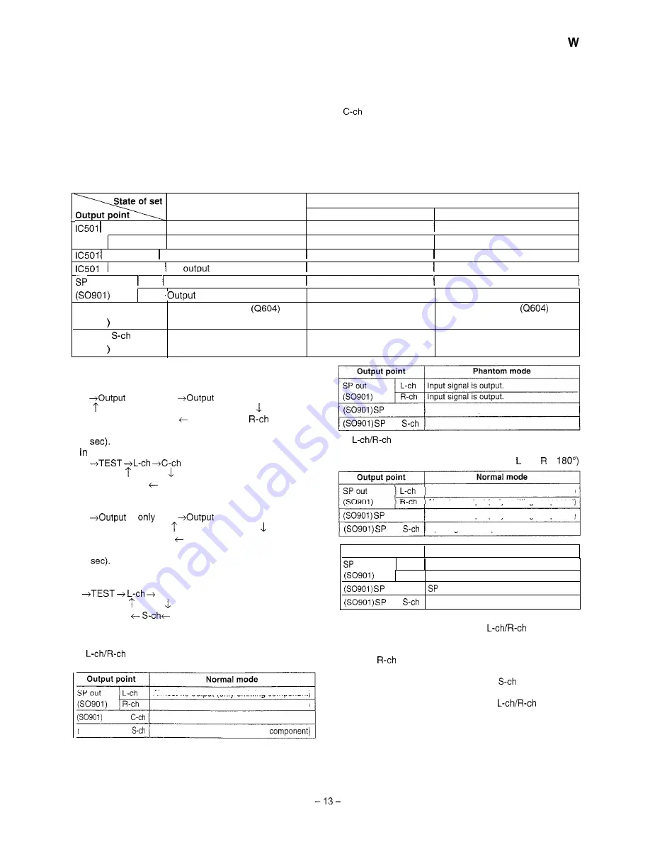
State of element output and terminal output in specific mode
Dolby Pro Logic
Bypass mode
12 pin L-out Output enabled state
Dolby Pro Logic On mode
Normal mode
Phantom mode
Output enabled state
Output enabled state
11 pin R-out Output enabled state
Output enabled state
9 pin C-out No output
Output enabled state
Output enabled state
No output
10 pin S-out No
Output enabled state
Output enabled state
I
OUT
L-ch Output enabled state
Output enabled state
Output enabled state
R-ch
enabled state
Output enabled state
Output enabled state
SP OUT C-ch
No output in MUTE
state
Output enabled state
No output in MUTE
state
(SO901
SP OUT
No output in MUTE (Q603) state
Output enabled state
Output enabled state
(SO901
Test tone output
l
Pro Logic ON Normal mode
Press the remote control TEST TONE button.
of only L-ch
of only C-ch
Output of only S-ch
Output of only
The test tone (noise) is repeatedly output for output period
(2
this case the following indication appears repeatedly.
S-ch
R-ch
l
Pro Logic ON Phantom mode
Press the remote control TEST TONE button.
of
L-ch
of only R-ch
Output of only S-ch
The test tone (noise) is repeatedly output for output period
(2
In this case the following indication appears repeatedly.
R-ch
Relation between VIDEO IN input and output in Pro Logic
ON state
(1)
same phase input into VIDEO IN input jack in
VIDEO Function mode
Almost no output (only omitting component)
Almost no output (only omitting component)
SP out
Input signal is output.
(50901) SP out
Almost no output (only omitting
out C-ch
SP cut, no output
out
Almost no output (only omitting component)
(2)
reverse phase input into VIDEO IN input jack in
VIDEO Function mode
(Reverse phase: Phase difference between and is
Almost no output (only omitting component)
Almost no output (only omitting component)
out C-ch
Almost no output (only omitting component)
out
Input signal is output.
Output point
Phantom mode
out
L-ch
Almost no output (only omitting component)
R-ch
Almost no output (only omitting component)
out C-ch
cut, no output
out
Input signal is output.
l
Accordingly, if you want to output signal waveform to C-ch SP
out, give the same phase input into
INPUT in the
Pro Logic Normal mode.
If one of channels receives input, C-ch does not output. Only
L-ch or
outputs.
l
If you want to output signal waveform to
SP out, you can
use either Normal mode or Phantom mode. However, 180”
reverse phase input must be given to
INPUT.
Summary of Contents for CD-C471 W
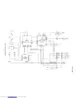
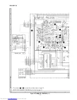
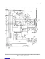
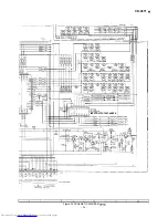
Page 16: ... I I Ill I i c r __ __ I Figure 16 BLOCK DIAGRAM 2 3 16 ...
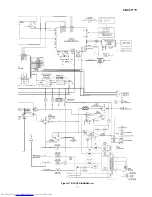
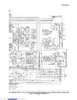
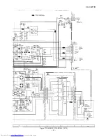
Page 17: ...CD C471 W w UTER lC56115621563 N5M4558L lC562 1 2 Figure 17 BLOCK DIAGRAM 3 3 17 ...
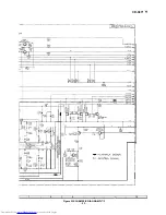
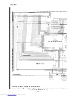
Page 36: ... POWER PWB B 1 MAII IUPWB P33 7 A 1 2 3 4 5 6 Figure 36 WIRING SIDE OF P W BOARD 6 8 36 ...
Page 54: ...CD C471 W MEMO 54 ...
Page 70: ......
Page 71: ...CD C471 W MEMO ...


