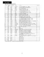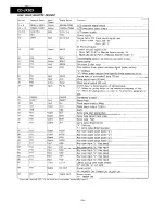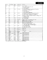
Since the adjusting procedure differs from that described in “ADJUSTMENT PROCEDURES OF AUDIO PRODUCTS”, refer to
the Service Manual.
All the semivariable resistors must be set in the mechanical center position
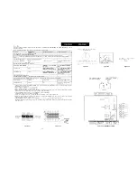
Test Stage
Parts
Value/Adjusting Method
Instrument
Set TEST MODE and
the
to the center
Set Test MODE (make sure that the laser lamp
_
_
a disc, set to TEST MODE 2. (Check to see that focus
is ON.: The disc does not rotate, and a whining sound is
heard.)
Set TEST MODE 3 (Spin
is turned on. and the disc rotates)
Tracking
balance
I
i
‘1 (See Fig. 21-l)
Pin 6
and
4
of TP751
Set TEST MODE 4
turned
Check
the HF signal waveform.
circuit is used.)
Set TEST MODE 5, and make
that track No. and time are displayed.
Stick black tape on the disc, and play that section (Fig. 22-l). (Any mode other than the test mode is acceptable.)
Focus offset
VR700
'4 (Fig. 22-Z)
Pin 6
and
Tracking offset adj.
o
f
T
P
7
5
1
‘ 5
'6
Pin 6
and pin 4
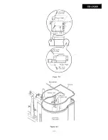
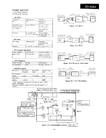
Figure 22-1
1
Adjust to obtain vertically symmetrical waveform (Fig. 21-I) with respect to reference DC level. The reference level is
[Amplitude of 0.5 to 1.5 Vpp)
2 Input oscillation frequency: 1.3
100
rms
3 Input oscillation frequency: 1.5
300
rms
4 Watch the monitor. Adjust so that the error waveform is uniform and minimum (Fig. 22-2) and the audio output is played
properly without noise (track jump noise) and free from skips and pauses.
5 The appropriate measuring range of the oscilloscope is
and
Connect the trigger to pin 14 (HFOK) of CNP700.
Trigger the coupling at DC and (-) slope. Observe the waveform in the normal trigger mode.
6 Watch the monitor. Adjust so that the error waveform is uniform and
(Fig. 22-2) and the audio output is played
properly without noise (track jump noise).
7 The appropriate measuring range of the oscilloscope is
and
The trigger is the same as
(Reference) When the noise element of the error waveform is large and unclear, observe the waveform through the low-pass
filter (Fig. 22-3).
Figure 22-2
P I C K U P
Figure 22-3
TP75 1
FOCUS
T R A C K I N
FOCUS
TRACK IN
O F F S E T
O F F S E T
G A I N
G A I N
Figure 21-l
Figure 21-2
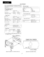
Figure 22-4 ADJUSTMENT POINTS
Summary of Contents for CD-JX20X(GY)
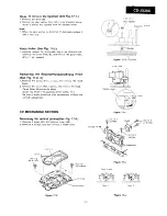
Page 11: ...Figure 15 1 Rear cabinet ILeft Side Figure 15 2 15 ...
Page 28: ...h ...
Page 29: ...1 I ...
Page 32: ...6 b ...
Page 34: ...0 0 0 a7 0 0 I t I ...
Page 35: ...I 16 ...
Page 36: ...J ...
Page 37: ...r l t I I I ...
Page 39: ......
Page 41: ... M 7 0 2 PWB F 1 2 3 4 5 6 I Figure 61 CD MECHANISM EXPLODED VIEW 61 ...
Page 44: ...E ...


