background image

– 15 –

CD-XP700H

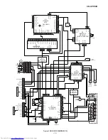
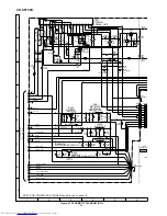
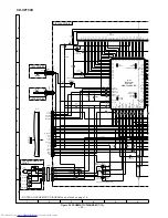
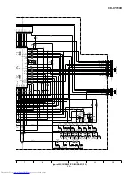
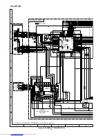
 Figure 15 BLOCK DIAGRAM (1/3)

CNP7

CNP6

Q2

+3.3V

+5V

+5V

CONT5

MP3 CE

MP3 CL

DVDD1

DVDD2

DVDD3

DVDD4

DVDD5

DVDD6

X2

X1

LRSY

ADDATA

ADBCK

ADLRCK

C2FIN

CKIN(16M)

CKOUT

DATAIN

DATACK

CONT3

CONT4

SLDO

SPDO

FDO

TDO

+5V 

+6.5V 

TO DISPLAY SECTION

CLAMP SW

WRQ

CE

DO

CLK

DI

CD RES

OPEN/CLOSE

DISC NO.

SUB-CE

MPEG POWER

DRF

CNS4

BI4

CNP4

M2

SLED

MOTOR 

M1

SPINDLE

MOTOR

M

M

TRACKING  COIL

FOCUS  COIL

PICKUP UNIT 

FIN1 A

FIN2 B

TIN1 E

TIN2 F

VVDD

ADAVDD

VDD

LVDD

RVDD

XVDD

VDD5V

LDS

LDD

Q1

LASER

DRIVER

VCC3

SYS-CE

SYS-CL

SYS-DO

SYS-DI

VCC2

VCC4

VCC

VCC

VCC

DOEB

DCASUB

DCASLB

VCC1

IC2

M63001FP

FOCUS/TRACKING/
SPIN/SLED DRIVER

TO MAIN SECTION

R-CH

L-CH

AGND

DGND

DGND_DRIVER

+5V(DIG.) (+B7)

+5V(ANL) (+B8)

+6.5V (+B4)

RCHO

RVSS

LVSS

LCHO

IC1

LC78645NE

CD SERVO

-

+

M

SW1

OPEN/

CLOSE

XL1

33.8688 MHz

XL2

4.19 MHz

5

4

3

2

3

2

5

4

7

8

6

1

1

6

7

8

9

10

11

12

1

2

4

3

5

SW2

CLAMP

SW3

DISC

NUMBER

M3

T/T

UP/DOWN

LOADING

MOTOR

6

1

2

4

3

5

6

1

2

4

3

5

6

42

37

51

43

44

45

25

70

71

43

44

61

62

63 64 65

66

67

CE

CL

DI

DO

WRQ

RES

DEF

48

49

XOUT

XIN

68

77

79

80

18

38

41

46

47

7

27

8

9

10

19

75

20

21

22

23

26

60

54

52

50

1

4

5

6

7

15

16

26

27

2

17

25

4

3

2

1

79

80

80

9

7

5

51

31

21

11

68

61

OEB

CASUB

CASLB

45

43

44

41

42

38

39

35

29

22

21

14

8

40

18

24 23

28

SW4

PICKUP IN

+3.3V 

+3.3V 

+3.3V 

+5V 

+5V 

~

~

23

1

6

22

29 30

31

30

~

~

~

IC5

IX0542AW

MP3 SUB

MICROCOMPUTER

IC3

LC78683E

MP3

DECODER

FSYNC

CMDOUT

INTB

FSYNC

CMDOUT

INTB

VDD

M+

M–

PS–

PS+

SL-

SL+

VDD

AVDD

73

77

66

73

77

66

73

77

66

15

16 18 19

IC4

LC32V4265B

4M DRAM

11

10

26

27

MP3 CE

MP3 CL

MDATA0

MDATA0

MDATA7

~

MDATA8

MDATA15

ADRS8

RASB

WEB

ADRS7

ADRS0

MDATA3

75

76

6

40

IC7

SI3033LUS

REGULATOR

3.3V

IC6

SI3033LU

REGULATOR

3.3V

Q3
Q4
Q5

,

41 ,

33

40

~

53

60

~

~

,

42 , 50 ,

2

5

~

~

MDATA4

MDATA7

DWEB

DRASB

~

MDATA8

MDATA11

~

MDATA12

MDATA15

~

ADRS0

ADRS3

~

ADRS4

ADRS8

~

,

15

,

,

7

10

~

18

21

~

,

24

28

~

, 35

38

~

, 40

43

~

16

,

+

+

ZD1

Summary of Contents for CD-XP700H

Page 1: ... SERVICE MANUAL This document has been published to be used for after sales service only The contents are subject to change without notice SHARP CORPORATION In the interests of user safety the set should be restored to its original condition and only parts identical to those specified be used MINI COMPONENT SYSTEM MODEL CD XP700H CD XP700H Mini Component System consisting of CD XP700H main unit an...

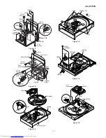
Page 2: ...el E1 x2 ø3x10mm F2 x1 F2 x1 E2 x1 F3 x1 E3 x1 E2 x2 Main PWB Transformer PWB Power PWB G2 x1 G1 x16 ø3x10mm Display PWB Open Cassette Holder Tape Mechanism J1 x1 ø3x10mm H1 x5 ø3x10mm Lug Wire Front Panel Headphones PWB L1 x3 3 L1 x3 Loading Tray 1 2 Loading Tray M1 x2 ø3x10mm M3 x2 CD Servo PWB M2 x1 M3 x2 Figure 7 6 CD Mechanism N2 x2 N1 x1 N1 x1 Loading Tray ...

Page 3: ...ront Panel A1 x1 8 1 2 Screw A2 x4 8 2 2 Tweeter 1 Screw B1 x2 8 2 STEP REMOVAL PROCEDURE FIGURE CP XP700H Screwdriver Driver should be pried away from Speaker Box A1 x1 Speaker Box Ass y A2 x4 ø4x12mm B1 x2 ø3x10mm Speaker Box Ass y Woofer Tweeter ...

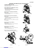
Page 4: ...e direction of the arrow B Note When installing the pinch roller pay attention to the spring mounting position How to remove the belt TAPE 2 See Fig 9 4 1 Remove the main belt D1 x 1 pc from the motor side 2 Remove the FF REW belt D2 x 1 pc How to remove the belt TAPE 1 See Fig 9 4 1 Remove the main belt E1 x 1 pc from the motor side 2 Remove the FF REW belt E2 x 1 pc How to remove the motor See F...

Page 5: ...ading motor See Fig 10 1 1 Bend the hooks A1 x 5 pcs to remove the loading motor Figure 10 1 ADJUSTMENT MECHANISM SECTION Driving Force Check Torque Meter Specified Value Play TW 2111 Tape 1 Over 80 g Tape 2 Over 80 g Torque Check Torque Meter Tape 2 Play TW 2111 30 to 80 g cm 30 to 80 g cm Fast forward TW 2231 70 to 180 g cm Rewind TW 2231 70 to 180 g cm Specified Value Tape 1 Specified Value Adj...

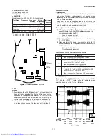
Page 6: ...us gain adjustment Tracking gain adjustment Adjustment Since this CD system incorporates the following automatic adjustment functions readjustment is not needed when replacing the pickup Therefore different PWBs and pickups can be combined freely Each time a disc is changed these adjustments are performed automatically Therefore playback of each disc can be performed under optimum conditions CHECK...

Page 7: ...racking OFF play at that specific point MEMORY key input Tracking ON play from that specific point STOP key input STOP IL isn t done VOL Last memory BAL CENTER P GEQ FLAT X BASS OFF To cancel Power OFF Sliding the PICKUP with button must only be in STOP mode MEMORY key input Adjustment result automatically will display as below for each 2 sec a FOFF_XX b TOFF_XX c TBAL_XX d TGAN_XX f FGAN_XX g RFL...

Page 8: ...T READ TUN PLL Unlock ER TU 00 TUN Error 01 PLL Unlock 02 03 CHECKING If CD changer mechanism error is detected CHECKING will be display instead of ER CD display ER CD will only be display when CD changer mechanism error had been detected for the 5 th times Speaker abnormal detection and B PROTECTION display In case speaker abnormal detection or B PROTECTION had occured it can be check by pressing...

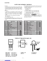
Page 9: ...ofarad As to electrolytic capacitor the expression capacitance withstand voltage is used CH TH RH UJ Temperature compensation ML Mylar type P P Polypropylene type Schematic diagram and Wiring Side of P W Board for this model are subject to change for improvement without prior notice REF NO DESCRIPTION POSITION SW716 TUNING TIME UP ON OFF SW717 REC PAUSE ON OFF SW718 MEMORY SET ON OFF SW719 TUNING ...

Page 10: ... 3 2 5 4 7 8 6 1 1 6 7 8 9 10 11 12 1 2 4 3 5 SW2 CLAMP SW3 DISC NUMBER M3 T T UP DOWN LOADING MOTOR 6 1 2 4 3 5 6 1 2 4 3 5 6 42 37 51 43 44 45 25 70 71 43 44 61 62 63 64 65 66 67 CE CL DI DO WRQ RES DEF 48 49 XOUT XIN 68 77 79 80 18 38 41 46 47 7 27 8 9 10 19 75 20 21 22 23 26 60 54 52 50 1 4 5 6 7 15 16 26 27 2 17 25 4 3 2 1 79 80 80 9 7 5 51 31 21 11 68 61 OEB CASUB CASLB 45 43 44 41 42 38 39 ...

Page 11: ...C R REC L REC POP REDUCE SWITCHING L T2 R T2 R T1 L T1 B7 B8 R L PHASE FM AM MPX IN STEREO AM RF IN AM OSC IN AM OSC OUT FM Q360 X OUT X352 4 5 MHz AM BAND COVERAGE AM TRACKING T303 T306 X351 456 kHz ZD351 5 1V MO ST VCO FM DET FM B GND AM IF CF351 IC303 LA1832S FM IF DET FM MPX AM IF AM MIX CF352 T351 CF302 CF301 Q301 FE301 FM FRONT END 21 4 24 2 1 8 18 17 3 9 10 18 11 16 3 15 10 9 7 23 14 12 13 ...

Page 12: ...10 B9 VDD VDD VDD CE DI DO XL700 4 194304 MHz BIAS T1 T2 AVDD SW701 SW705 SW711 SW725 SW727 SW729 KEY TO CD SERVO SECTION TO CD SECTION IC701 IX0541AW SYSTEM MICROCOMPUTER FL701 FL DISPLAY 27 85 80 33 45 93 14 92 1 2 4 5 6 7 8 14 18 2 78 70 5 1 3 2 1 11 6 7 1 5 8 100 33 31 37 26 15 46 1112 9 10 16 17 20 2122 2324 41 79 54 38 59 62 52 45 51 50 55 49 48 40 25 13 39 34 T F PT801 MAIN POWER TRANSFORME...

Page 13: ...1 C636 0 001 R614 3 3K Q602 KTC3199 GR R610 2 2K R612 390 R605 10K C609 1 50 C607 0 1 R607 3 9K C611 0 0022 C605 0 1 C613 1 50 C615 4 7 50 C617 1 50 C619 1 50 C621 1 50 C623 1 50 IC601 LC75341 AUDIO PROCESSOR C651 220P C652 220P R601 1K C653 220P C601 220 16 C6 0 0 C603 22 50 C608 0 1 C606 0 1 C6 0 0 C614 1 50 C616 4 7 50 C618 1 50 C620 1 50 C622 1 50 C624 1 50 CNP101 CNP102 C640 1 50 R620 22K C63...

Page 14: ...21 22 23 24 25 26 27 8 7 6 5 4 3 2 1 56K 56K ME Nor CrO2 RIPPLE ALC ALC Vcc MAIN PWB A1 1 3 CHASSIS GND 17 6 4 15 13 7 18 10 9 16 21 1 2 3 SWITCHING BIAS OSC BIAS B B B B B B B B B B B B 31 32 33 34 35 25 30 27 22 26 28 23 24 29 N C JK690 VIDEO AUX IN R693 33K R692 33K R690 6 8K C690 390P R691 6 8K C691 390P CNP601 3 P C601 220 16 C602 0 022 C603 22 50 C608 0 1 R604 10K C610 1 50 C606 0 1 R606 3 9...

Page 15: ...380 O R378 1K R372 1K R374 1K R373 1K C386 330P R395 47K R376 1K R386 22K R360 4 7K C383 47P C382 15P CH X352 4 5 MHz C381 12P CH R344 470 R399 33 C348 0 01 C347 0 022 CF301 R349 33 R348 680 R345 4 7K C346 0 022 C321 100 16 C345 0 022 FE301 FM FRONT END C397 0 022 R382 150 R381 10K C392 0 001 R380 1 5K C393 1 50 R379 2 2K C380 10 50 C394 47 25 C387 0 022 C385 0 01 L351 100 µH R377 47K R387 5 6K C3...

Page 16: ...C391 47 25 R383 5 6K R392 270 R385 5 6K Q360 KTA1266 GR R391 270 C395 0 022 C396 100 10 R359 1 8K ZD351 DZ5 1BSB L352 100 µH C384 0 001 386 30P R395 47K 376 1K R386 22K R360 4 7K R377 47K R387 5 6K C399 0 022 C398 100 10 R393 1K R388 3 9K ZDT21 DZ5 1BSB RT30 1K LT21 2 2 µH CT24 47 25 LT22 2 2 µH CT30 0 022 CT32 47 25 CT31 47 25 CT28 0 022 CT26 560P RT26 56K RT25 10K QT21 KTC3199 GR RT24 56K CT29 0...

Page 17: ...02 KTC3199 GR D906 DS1SS133 R919 1 8K C916 100 50 C918 100 50 ZD902 DZ150BSB R925 1 5K ZD903 DZ15BSB R926 1 5K D907 DS1SS133 Q904 KTC3199 GR Q903 KTC3199 GR C925 47 50 R937 56K R934 56K L902 R935 56K Q901 KTC3199 GR D905 DS1SS133 R920 1 8K C919 0 022 ML R921 1 5K R922 0 1 3W R908 1K R958 100 Fusible 1 4W C915 100 100 C911 100 100 C904 220P C903 220P R902 56K R901 56K C902 0 22 50 C901 0 22 50 R928...

Page 18: ... L920 0 29 µH L921 0 29 µH R955 6 8 R953 6 8 R954 6 8 R952 6 8 C941 0 022 C939 0 022 C937 0 022 C935 0 022 C940 0 022 C938 0 022 C936 0 022 C934 0 022 C943 0 001 C942 0 001 K801 K802 F805 T2 5A L 250V L841 LINE FILTER C844 0 0047 RL841 D846 DS1SS133 PT841 SUB POWER TRANSFORMER FW804 D845 D842 C842 470 35 D844 D843 HLD804B C843 0 047 ML C841 1000 6 3 Q841 KTC3199 GR R843 47K R842 1K R841 220K CNP80...

Page 19: ...Y S_MUTE SW_5V UNSW5 6 M_ 13V B_PROTECT LVL_DET A 10V SP_RLY D_GND REC PLAY T_T1 T2 T_BIAS DI CE CLK DO SP_DET 20dB 15 3 2 1 1 2 19 18 17 16 14 13 12 23 27 26 25 24 22 21 20 11 9 10 8 7 6 5 4 T2_PLAY SW T2 RUN MTR SOL2 SOL1 T1 RUN GND F_REC 8 7 2 3 6 1 5 4 NX NX NX NX NX NX NX TAPE MECHANISM PWB F TAPE MOTOR PLAY F PLAY CASSETTE SOLENOID SOLENOID PH 1 2 3 4 5 6 7 8 1 8 27 1 CNP601 P19 12 F TO MAIN...

Page 20: ...R713 1K R714 1K R715 1K R716 1K R717 100 R709 1K R769 1K C704 15P C705 18P XL700 4 194304 MHz 1 AW EM PUTER R739 1K R737 100 C720 0 022 R722 1K R736 1K R733 1K R718 1K R719 1K R720 1K R721 1K R756 4 7K 701 42VCJ R761 10K R768 10K R767 10K R766 10K R773 10K R759 5 6K R747 4 7K R791 4 7K R748 10K C702 220 10 C701 1 50 R795 1 5 L701 100µH D713 DS1SS133 D712 DS1SS133 D714 DS1SS133 R781 47K C715 0 01 C...

Page 21: ...VDD JITTC RFMON TE TEC FE TIN2 F TIN1 E FIN2 B FIN1 A RSVSS RFVDD RF EFMIN SLCIST SLCO 6 5 4 3 2 1 C F B A E VREF VCC 1 2 3 4 5 6 7 GND FO LD VR PD FO TR TR 1 2 3 4 5 6 7 8 CD SERVO PWB C 3 1 2 IC2 M63001FP LASER DRIVER CD MOTOR PWB D PICKUP UNIT B B IC7 SI3033LUS VOLTAGE REGULATOR C38 0 022 C39 0 1 C37 47 10 C44 100 10 R57 1 R56 10K R58 1 R54 820 R55 820 C43 100 10 CNP2 CNP1 C36 0 01 C2 0 01 C1 4...

Page 22: ... OVF CNTOK WOK VSS DVDD6 CRCF STDAT STCK STREQ VSS DVDD5 VSS DVDD4 VSS VSS DVDD2 AVSS VPDO VCOC VPRFR AVDD1 SBCK SFSY SBSY PW DVDD1 TEST2 CKOUT VSS CKIN 16M TEST1 C2FIN ADLRCK ADBCK ADDATA LRSY VSS VSS DCASLB DCASUB DOEB ADRS8 ADRS7 ADRS6 ADRS5 ADRS4 VSS VCC ADRS3 ADRS2 ADRS1 ADRS0 DRASB DWEB VCC VCC 6 5 4 3 2 1 7 1 2 3 4 5 6 MPEG POW SUB CE DISC NO CD RES O C CLAMP SW CL DI DO CE DRF WRQ CNS701 1...

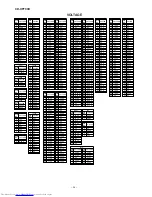
Page 23: ...0 V 0 V 0 V 2 1 V 2 1 V 1 6 V 4 9 V 3 0 V 1 6 V 0 V 0 V 4 9 V 4 9 V 1 8 V 2 1 V 2 1 V 0 V 0 V 0 V 0 V 0 V 0 V 0 V 0 V 4 2 V 0 V 2 1 V 2 1 V 4 9 V 3 7 V 3 7 V 9 8 7 6 5 4 3 2 1 30 29 28 27 26 25 24 23 22 21 20 19 18 17 16 15 14 13 12 11 10 40 39 38 42 41 37 36 35 34 33 32 31 PIN NO VOLTAGE IC2 3 25 V 1 66 V 1 66 V 1 66 V 1 66 V 3 26 V 1 66 V 1 66 V 1 66 V 1 66 V 0 V 0 V 3 13 V 3 26 V 0 V 0 V 0 V 0 ...

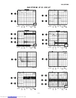
Page 24: ... 51 15 500 ms div NORM 20 kS s 2 1 Record Length Smoothing ON CH1 0 000 V CH2 0 000 V Main 100 K Zoom 2 K Mode NORMAL Type EDGE CH2 Delay 2 924 ms Hold off 0 2 µs CH3 0 00 V CH4 0 00 V BW FULL Trigger Filter Offset 1 IC1 21 6 IC1 22 T T TE DRF Stopped CH1 10 V DC 10 1 CH2 1 V DC 10 1 100 ms div 100 ms div NORM 100 kS s 2 1 Record Length Smoothing ON CH1 0 0 V CH2 0 00 V Main 100 K Zoom 2 K Mode NO...

Page 25: ...KA0004AFZZ TROUBLESHOOTING When the CD does not function When the CD section does not operate when the objective lens of the optical pickup is dirty this section may not operate Clean the objective lens and check the playback operation When this section does not operate even after the above step is taken check the following items Remove the cabinet and follow the trouble shooting instructions Trac...

Page 26: ...s servo activated Waveform drawing Figure 39 2 Pins 7 11 79 and 80 on IC1 Check the laser diode driver Q1 peripheral circuit When a disc is loaded start playback operation 2 Does DRF change from L to H Is the disc rotating 3 Is the HF waveform normal Waveform drawing Figure 39 3 Check the spin system If the disc is spinning and a HF waveform is generated DRF will go H Figure 39 1 Check the laser d...

Page 27: ...ctivated Check the peripheral circuits at pins 14 15 and 20 on IC1 and CNS1A B If the waveform shown in Figure 40 1 appears and soon after NO DISC appears 2 Tracking system check Check the TE waveform at pin 15 on IC1 A normal jump operation cannot be completed or the beginning of the track cannot be found Check the around pin 20 on IC1 Initialization is possible but play is not possible Data cann...

Page 28: ...0 2 µs CH3 0 00 V CH4 0 00 V BW FULL Trigger Filter Offset CH1 v DIV 500 mV 1999 04 05 17 33 17 Is pin 52 C2F on IC1 L Yes No The HF waveform is normal and the time is displayed normally but no sound is produced Or the sound has dropouts 5 Others There are too many error flags on a damaged disc which makes error correction impossible Check again using a known good disc 1 When playing at normal spe...

Page 29: ...GNMENT P1 1G S1 S2 S3 S4 a b k j h f m d g p e n r c Dp a b k j h f m d g p e n r c Dp a b k j h f m d g p e n r c Dp a b k j h f m d g p e n r c Dp a b k j h f m d g p e n r c Dp a b k j h f m d g p e n r c Dp a b k j h f m d g p e n r c Dp a b k j h f m d g p e n r c Dp S1 S2 S3 S4 S1 S2 S3 S4 S1 S2 S3 S4 S1 S2 S3 S4 S1 S2 S3 S4 S1 S2 S3 S4 S1 S2 S3 S4 2G 3G 4G 5G 6G 7G 8G 9G P2 P3 P4 P5 P6 P7 P...

Page 30: ...A AC Power Supply Cord Bushing Brown Blue Sub Power Transformer Transformer PWB WIRING OF PRIMARILY SUPPLY LEADS FOR U K ONLY If any one of the bands shown in Fig 54 is removed for some reason be sure replace it to the original position and same appearance as before Figure 54 ...

Page 31: ...ical type without lead wire VC MN Cylindrical type without lead wire VC TV Square type without lead wire VC TQ Square type without lead wire VC CY Square type without lead wire VC CZ Square type without lead wire VC J The 13th character represents capacity difference J 5 K 10 M 20 N 30 C 0 25 pF D 0 5 pF Z 80 20 If there are no indications for the electrolytic capacitors error is 20 Resistors VRD ...

Page 32: ...DS1SS133 LED701 VHPSLR342VCJ1 J AC LED Red SLR342VCJ LED703 704 VHPA503BC2E 1 J AN LED White A503BC2E ZD1 VHEMA8033 1 J AC Zener 3 3V MA8033 ZD351 VHEDZ5R1BSB 1 J AC Zener 5 1V DZ5 1BSB ZD801 802 VHEDZ6R2BSA 1 J AB Zener 6 2V DZ6 2BSA ZD803 VHEDZ300BSB 1 J AB Zener 30V DZ30BSB ZD852 VHEDZ8R2BSB 1 J AB Zener 8 2V DZ8 2BSB ZD902 903 VHEDZ150BSB 1 J AB Zener 15V DZ15BSB ZDT21 VHEDZ5R1BSB 1 J AC Zener...

Page 33: ...50J J AA 15 pF CH 50V C383 VCCSBT1HL470J J AA 47 pF 50V C384 VCKYMN1HB102K J AA 0 001 µF 50V C385 VCTYMN1CY103N J AA 0 01 µF 16V C386 VCKYMN1HB331K J AA 330 pF 50V C387 VCTYMN1EF223Z J AA 0 022 µF 25V C388 VCKYMN1HB102K J AA 0 001 µF 50V C389 VCKYBT1HB102K J AA 0 001 µF 50V C391 VCEAZA1EW476M J AB 47 µF 25V Electrolytic C392 VCKYMN1HB102K J AA 0 001 µF 50V C393 VCEAZA1HW105M J AB 1 µF 50V Electrol...

Page 34: ...3J J AA 47 kohms 1 8W R109 110 VRD MN2BD472J J AA 4 7 kohms 1 8W R111 VRD ST2CD153J J AA 15 kohms 1 6W R112 VRD MN2BD153J J AA 15 kohms 1 8W R113 114 VRD ST2CD102J J AA 1 kohm 1 6W R115 116 VRD ST2CD560J J AA 56 ohms 1 6W R117 118 VRD MN2BD104J J AA 100 kohm 1 8W R119 120 VRD MN2BD392J J AA 3 9 kohms 1 8W R121 122 VRD MN2BD123J J AA 12 kohms 1 8W R123 124 VRD MN2BD562J J AA 5 6 kohms 1 8W R126 127...

Page 35: ...ST2CD563J J AA 56 kohms 1 6W R937 VRD ST2CD563J J AA 56 kohms 1 6W R938 941 VRD RT2HD100J J AA 10 ohm 1 2W R942 943 VRS VV3DA391J J AC 390 ohms 2W R944 945 VRD ST2EE152J J AA 1 5 kohms 1 4W R946 VRD ST2CD473J J AA 47 kohms 1 6W R947 VRD ST2CD153J J AA 15 kohms 1 6W R948 VRD RT2HD4R7J J AA 4 7 ohms 1 2W R949 VRD ST2CD102J J AA 1 kohm 1 6W R950 VRD ST2CD683J J AA 68 kohms 1 6W R952 955 VRD ST2EE6R8J...

Page 36: ...r LED Timer 201 6 GDORF0112AWSA J AE Holder Cassette Tape 1 201 7 GDORF0113AWSA J AE Holder Cassette Tape 2 201 8 HDECQ0834AWSA J AE Panel Cassette Tape 1 201 9 HDECQ0835AWSA J AE Panel Cassette Tape 2 201 10 HDECQ0869AWSA J AM Panel Amp 201 11 HDECQ0844AWSC J AE Ring Play Stop 201 12 JKNBZ0882AWSA J AG Button RDS 201 13 JKNBZ0862AWSA J AH Button Volume 201 14 JKNBZ0863AWSA J AK Button Operation 2...

Page 37: ...SSAKA0007AWZZ J AB Polyethylene Bag Accessories 5 SPAKZ0885AWZZ J AB Mirror Mat Sheet 6 RRMCG0320AWSA J AR Remote Control 6 1 GFTAB1022AWSB J AK Battery Lid Remote Control 7 QANTL0008AWZZ J AH AM Loop Antenna 8 92LFANT1535A J AF FM Antenna 9 TCAUZ0129AWZZ J AB Caution Transport 10 TINSE0455AWZZ J AF Operation Manual For U K 10 TINSZ0800AWZZ J AR Operation Manual Except for U K 11 TINSZ0805AWZZ J A...

Page 38: ...CD XP700H A B C D E F G H 1 2 3 4 5 6 Figure 7 CD MECHANISM EXPLODED VIEW 7 306 1 701 304 701 302 301 702 303 M1 703x2 305x2 SW4 M2 305 PWB D 306 2 306 3 306 704 CD XP700H ...

Page 39: ... ROLLER ASS Y BELT CONNECTION 614x11 614x3 614 207 M4 248 234 212 614 213 245 211 605x2 PWB B1 219 220 FL701 608x16 PWB B2 602 201 PT801 612x4 621x2 252 247x2 247x8 PWB A2 PWB A3 250 614x2 201 20 201 21 618x2 242x2 203 203 2 203 1 IC852 IC901 IC851 IC853 615x3 Silicon Grease Silicon Grease 208 603 230 611x2 611x2 210 228 231 603 227 209 208 1 208 2 208 3 208 4 208 5 208 6 208 7 208 8 208 9 208 10 ...

Page 40: ...215 241 249 609x2 205 609x2 M3 SW3 M3 SW2 SW1 251 PWB E 226 224 223 229 236 237 236 222 221 218 240 225 239 238 CD MECHANISM 216 251 235 PWB C 251 251 251 204 214 232 619x2 613 233 620 620 206 601 258 Figure 9 CABINET EXPLODED VIEW 2 2 9 CD XP700H ...

Page 41: ... Figure 10 SPEAKER EXPLODED VIEW 10 CP XP700H 902 909 909 905 903 C1 2 901 906 908x4 907x2 904x2 904x2 SP3 4 SP1 2 SP1 2 WOOFER BK RD SP3 4 C1 2 TWEETER Capacitor 2 7 µF 100 V N P C1 2 SP3 4 TWEETER SP1 2 WOOFER Capacitor 2 7 µF 100 V N P ...

Page 42: ...9AWZZ Caution Transport 10 TiNSE0455AWZZ Opration Manual 11 TiNSZ0805AWZZ Quick Guide 12 TLABE0646AWZZ Label Bar Code CP XP700H CD XP700H 1 SPAKA0337AWZZ Packing Add Top Bottom 2 SSAKH0078AWZZ Polyethylene Bag Speaker 13 TLABZ0159AWZZ Label Feature Tape 1 14 TLABZ1134AWZZ Label Feature Tape 2 15 TLABZ0605AWZZ Label Saving Energy 16 TGAN 3170UMZZ Warranty Card 17 Battery Not Replacemenr Item A B B ...

Page 43: ...CD XP700H MEMO 12 ...

Page 44: ...red in a retrieval system or transmitted in any form or by any means electronic mechanical photocopying recording or otherwise without prior written permission of the publisher A0204 300DS HA M SG SK SHARP CORPORATION AV Systems Group Audio Systems Division Higashihiroshima Hiroshima 739 0192 Japan Printed in Japan ...

Reviews: