Rankirw
(A,BorC)
t
roz-ara
PRINTER
UNIT
<
Printer head ranking position>
After
the above procedure,
adjust
by means of the
22-
Kohms protentiometer
so that an optimum
print quality is
obtalned.
The circuit has been so designed as to attain the
best result with the potentiometer
set at its midway_
Therefore,
existence of aremarkable
print density variation
might involve the following problems:
1.A>p
in head performance
2_~ality
change in the termal recording paper
3.
Throuble
in the thermal control circuit
1. When VR density Idjustment
is
needed
A) After
replacement
has been made in same electronic
component
parts inside the solid line.
B) When service request is placed from the user claiming
that print density is too low or high.
2. Print density control method
•
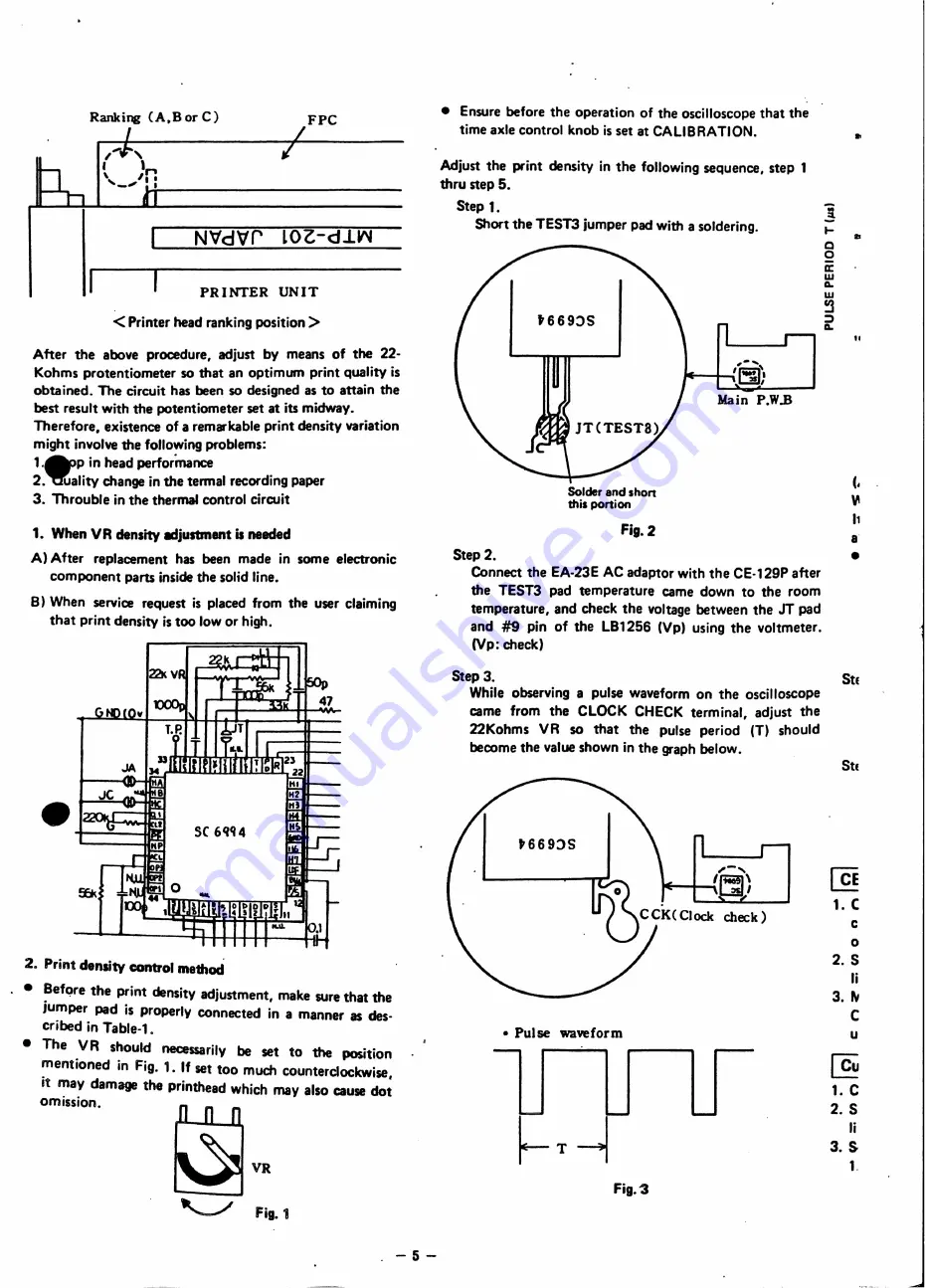
Before the print density adjustment,
make sure that the
jumper
pad is properly connected
in a manner
as des-
cribed in Table-1.
•
The
VR
should
necessarily
be set
to
the
position
mentioned
in Fig. 1. If set too much counterciockwise,
it may damage the printhead which mayaiso
cause dot
omission.
~VR
"-.J
FiS_'
. - 5-
•
Ensure before the operation
of the oscilloscope that the
time axle control knob is set at CALIBRATION.
Adjust the print density in the fOllowing sequence,
step 1
thru step 5.
Step 1.
Short the TEST3 jumper pad with a soldering.
t669:>S
,-,~
'1iiOn,
_.-
I
'LJ!I,
Solder and sho"
thispo"ion
Fig.2
Step 2_
Connect the EA-23E AC adaptor with the CE-129P after
the TEST3
pad temperature
came down to the room
temperature,
and check the voltage between the
JT
pad
and
#9
pin of the lB1256
(Vp) using the voltmeter.
(Vp: check)
..
~
I-
..
0
2
a:
w
11..
W
~
:)
11..
11
(,
~
11
a
•
Step 3.
StE
While observin9 a pulse waveform
on the oscilloscope
came
from
the
CLOCK CHECK terminal,
adjust
the
22Kohms
VR
so that
the
pulse
period
(T) should
become the value shown in the graph below.
t669:>S
• Pulse
waveform
Fig.
'3
StE
@
1. C
c
o
2. S
li
3. ~
C
u
~
1. C
2. S
li
3. S
1.
Do not sale !


