background image

EN-9

ENGLISH

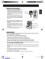
REMOTE CONTROL

REMOTE CONTROL DISPLAY

18
19
20

21

22

23

24

25

26

27

12
  9

10
11

13
14
15
16

17

  1

  2

  3

  4
  5

  6
  7

  8

  1  Tramsmitter
  2  Display 

AIR CON MODE ONLY

  3  A/C Button
  4  TEMP Button
  5  MAX COOL Button
  6  MODE Button
  7  SLEEP Button
  8  ON TIMER Button

ION MODE ONLY

  9  ION Button
  10  MAX DENSITY Button
  11  REFRESH Button

COMMON

  12  OFF Button
  13  FAN Button
  14  LOUVERS Button
  15  CANCEL Button
  16  OFF TIMER Button
  17  RESET Button

  18  MODE Symbols


: COOL 

: DEHUMIDIFICATION


: FAN  

: VENTILATION

  19  REFRESH Symbol
  20  MAX COOL Symbol
  21  ION GENERATOR Symbol
  22  MAX DENSITY Symbol
  23  SLEEP Symbol
  24  FAN SPEED Symbols


: AUTO 

: Quiet


: Low  

: High

  25  Temperature  and  timer  count 

down indicator

  26  Transmitting Symbol
  27  ON TIMER/OFF TIMER Symbol

CV-2P13SX_en.indd   9

11.3.3   5:58:15 PM

Summary of Contents for CV-2P10SX

Page 1: ... ACONDICIONADOR DE AIRE PARA HABITACIÓN TIPO PORTÁTIL MANUAL DE INSTALACIÓN Y FUNCIONAMIENTO Device of this mark is a trademark of Sharp Corporation Plasmacluster is a registered trademark or a trademark of Sharp Corporation This product can also be used as an ion generator CV 2P13SX_cover indd 1 10 11 26 11 44 42 AM ...

Page 2: ...CV 2P13SX_cover indd 2 10 11 26 11 44 42 AM ...

Page 3: ...UTIONS EN 4 LOCATION EN 7 INCLUDED EN 7 PART NAMES EN 8 INSTALL WINDOW PANEL EN 10 INSTALLATION AND REMOVAL OF EXHAUST HOSE EN 14 PRE OPERATION CHECKS EN 16 USE FOR AIR CONDITIONER COOL MODE EN 18 DEHUMIDIFICATION MODE EN 18 FAN MODE EN 19 VENTILATION MODE EN 19 TO CHANGE AIR FLOW DIRECTION EN 20 MAX COOL OPERATION EN 21 SLEEP OPERATION EN 21 TIMER OPERATION EN 22 USE FOR ION GENERATOR ION GENERAT...

Page 4: ...butor ACCESSORIES ADDITIONAL CUSTOMER INFORMATION TO WRITE For service problems warranty information missing items and other assistance Sharp Electronics Corporation Customer Assistance Center 1300 Naperville Drive Romeoville IL 60446 1091 TO ACCESS THE INTERNET www sharpusa com Please provide the following information when you write or call model number serial number date of purchase your complet...

Page 5: ...ll be the sole and exclusive remedy available to the purchaser Correction of defects in the manner and for the period of time described herein shall constitute complete fulfillment of all liabilities and responsibilities of Sharp to the purchaser with respect to the Product and shall constitute full satisfaction of all claims whether based on contract negligence strict liability or otherwise In no...

Page 6: ...e to confirm the power plug func tions normally This power plug must only be plugged into an appropriate wall socket Do not use in conjunction with any extension cords Push the power plug securely into the socket and make sure it is not loose Do not pull deform or modify the power supply cord or immerse it in water Pulling or misuse of the power supply cord can result in damage to the unit and cau...

Page 7: ...may be reduced or stop completely Place the unit on a level surface Placing the unit on a level surface to avoid water spring out into the room WARNING ABOUT GROUNDING Improper use of the grounding plug can result in the risk of electric shock This appliance must be grounded In the event of an electrical short circuit ground ing reduces the risk of an electric shock by providing a less resistant c...

Page 8: ...r will be blown out from the Exhaust air outlet but this is normal and does not indicate a problem with the unit This unit blows the warm air generated by the unit outside the room via the ex haust hose while in cool mode Accordingly the same amount of air as that is blown out will enter the room from outside through any openings into the room When cooling operation is performed at high humidity c...

Page 9: ...undation to minimize noise and vibration For safe and secure positioning place the unit on a smooth level floor strong enough to support the unit This will also help to avoid water spilling out into the room The unit has casters to aid placement but it should only be rolled on smooth flat surfaces Use caution when rolling on carpet surfaces Do not attempt to roll the unit over objects The unit mus...

Page 10: ...ATOR Lamp blue 10 Air inlet REAR VIEW NOTE Actual unit might vary slightly from above illustration FRONT VIEW 11 Exhaust air outlet 12 Window adapter 13 Exhaust hose 14 Remote control hook 15 Air filter 16 Grill 17 Air inlet 18 Drainpipe and stopcock 19 Power plug 20 Casters 4 1 2 3 4 5 6 7 8 9 10 10 10 PART NAMES 11 12 13 14 15 16 17 18 19 20 CV 2P13SX_en indd 8 11 3 3 5 58 14 PM ...

Page 11: ...tton 10 MAX DENSITY Button 11 REFRESH Button COMMON 12 OFF Button 13 FAN Button 14 LOUVERS Button 15 CANCEL Button 16 OFF TIMER Button 17 RESET Button 18 MODE Symbols COOL DEHUMIDIFICATION FAN VENTILATION 19 REFRESH Symbol 20 MAX COOL Symbol 21 ION GENERATOR Symbol 22 MAX DENSITY Symbol 23 SLEEP Symbol 24 FAN SPEED Symbols AUTO Quiet Low High 25 Temperature and timer count down indicator 26 Transm...

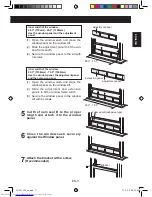
Page 12: ...he window panel Side A will now be at the top as indicated in the diagram 3 Cut the foam seal A to the proper length and attach it to the window stool 4 Attach the window panel to the window stool Make sure that the exhaust cover is attached to the window panel Inner width of the window 21 3 540mm 28 3 718mm Use the window panel The window panel cannot be installed in windows less than 21 3 540mm ...

Page 13: ...adjustment panel and the extension panel 1 Open the window sash and place the window panel on the window sill 2 Slide the adjustment and extension panels to fit the window frame width 3 Secure the window panel to the window sill with 4 screws 5 Cut the foam seal B to the proper length and attach it to the window panel 6 Close the window sash securely against the Window panel 7 Attach the bracket w...

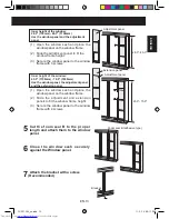
Page 14: ...seal A adhesive type to the proper length and attach it to the window frame 4 Install the window panel into the win dow frame Make sure that the exhaust cover is attached to the window panel Inner height of the window 21 3 540mm 28 3 718mm Use the window panel The window panel cannot be installed in windows less than 21 3 540mm high as you will be unable to shut the exhaust cover 1 Cut the window ...

Page 15: ...he adjustment panel and the extension panel 1 Open the window sash and place the window panel on the window frame 2 Slide the adjustment and extension panels to fit the window frame height 3 Secure the window panel to the window frame with 4 screws 5 Cut the foam seal B to the proper length and attach them to the window panel 6 Close the window sash securely against the Window panel 7 Attach the b...

Page 16: ... they click 3 Slide and open the exhaust cover on the window panel and attach the win dow adapter Double hung sash window Surface of window adapter marked TOP should be at the top Sliding sash window Surface of window adapter marked TOP should be on the window frame side The exhaust hose should be as short as possible for operational efficiency however it must not be twisted or bent Unacceptable A...

Page 17: ...ndow adapter by pushing down two PUSH markings and slide and close the exhaust cover in the win dow panel 2 Remove the exhaust hose from the unit Lift up and remove the exhaust hose from the unit by pushing on the two projections Projection PUSH Exhaust hose CV 2P13SX_en indd 15 11 3 3 5 58 18 PM ...

Page 18: ...long time re move the batteries from the remote control Battery cover PRE OPERATION CHECKS POWER PLUG CHECK This unit uses a fused power plug Always check the power plug before use 1 Press the RESET button 2 Insert the power plug into the wall sock et 3 Press the TEST button You will hear a CLICK if the circuit breaker is functioning correctly 4 Press the RESET button until you hear another CLICK ...

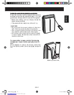
Page 19: ...dow to direct sun light This may adversely affect its operation Use of certain fluorescent lamp in the same room may interfere with transmission of the signal Do not leave the remote control in direct sunlight or near a heater Protect the remote control from moisture and shock To prevent the remote control from being misplaced hook it to the unit when not in use When attached to remove the remote ...

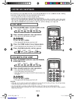
Page 20: ... will light The temperature cannot be set The fan speed is preset to AUTO and cannot be changed TO TURN OFF Press the OFF button The green AIR CON lamp will turn off NOTES Although you can also operate dehumidification mode without the exhaust hose the unit generates heat during operation and the room temperature will rise It is also possible to operate in dehumidification mode with hose not inclu...

Page 21: ...speed QUIET LOW HIGH VENTILATION MODE The unit ventilates the air to outdoors 1 Press the MODE button to select VENT mode COOL DEHUM FAN VENT 2 Press the A C button to start operation The green AIR CON lamp will light The temperature cannot be set TO TURN OFF Press the OFF button The green AIR CON lamp will turn off 3 Press the FAN button to set fan speed Although the louvers are closed and no air...

Page 22: ...rizontal louvers are positioned at the lowest position in the COOL or DEHUMIDIFICATION mode for an extended period of time condensation may result NOTE During VENTILATION mode UP DOWN air flow direction cannot be changed LEFT RIGHT AIR FLOW DIRECTION Hold the vertical louver as shown in the diagram and adjust the air flow direction CAUTION Do not adjust the vertical louvers to the extreme left or ...

Page 23: ...eration is set the temperature setting is automatically adjusted to prevent the room from becoming too cold 1 Press the SLEEP button during cooling mode The remote control displays The orange TIMER lamp will light The unit will stop operating after 8 hours The fan speed setting is set to AUTO TO CANCEL Press the SLEEP button The orange TIMER lamp will turn off NOTES One hour after the SLEEP operat...

Page 24: ... OFF TIMER and ON TIMER can not be set together If a power failure occurs while the OFF TIMER or ON TIMER is set the TIMER setting will be can celled and will not be retrieved even after the power is restored When the temperature is set during timer setting the temperature will show in the display for 5 sec onds and then return to the timer display OFF TIMER 1 Press the OFF TIMER button and set th...

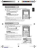
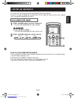
Page 25: ...ependently There is no need to install the exhaust hose Hot air will not come out from the exhaust hose during ION GENERATOR mode 1 2 ION GENERATOR MODE Note for ION GENERATOR MODE The ion generator inside the unit releases Plasmacluster ions into the room Plasmacluster ions will reduce airborne mold Plasmacluster is SHARP s original technology For more information please check our press release s...

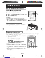
Page 26: ...lled in 30 minutes and the unit will return to the original settings MAX DENSITY operation and REFRESH operation can not be used together USE FOR ION GENERATOR TO CHANGE AIR FLOW DIRECTION UP DOWN AIR FLOW DIRECTION 1 Press the LOUVERS button The horizontal louvers will swing 2 Press the LOUVERS button again to stop the desired position CAUTION Never attempt to adjust the horizontal louvers manual...

Page 27: ...fective for reducing smell of tobacco smoke etc but may not always be effective for every kinds of odor Depending on the volume of odor distance between this unit and clothes and operating time this unit may not reduce the odor enough OFF TIMER OPERATION 1 Press the OFF TIMER button and set the time as desired The orange TIMER lamp will light The time setting will count down to show the re maining...

Page 28: ...pcock securely to the drainpipe MAIN UNIT OPERATION 1 1 Press the POWER button to start opera tion The mode will change as you press the button within 5 seconds In cool mode the unit will operate at its last cooling settings If the unit has been unplugged since it was last operated it will resume opera tion in the cooling mode set at 68 F The fan speed set to AUTO TO TURN OFF Press the POWER butto...

Page 29: ...e filter Doing so may result in serious damage to the unit CLEANING THE UNIT AND THE REMOTE CONTROL Wipe them with a soft dry cloth or with a cloth moistened with a mild soap Carefully re move any residue by wiping with a damp cloth and dry completely Avoid splashing water onto the unit Water can dangerously damage the electrical insula tion Never use harsh chemicals or abrasive cleaners on any pa...

Page 30: ...d or bent SOUNDS The unit may seem rather loud for the first 2 to 3 minutes when the unit is turned on This is the sound of the compressor starting up and is perfectly normal A soft swishing noise can be heard immediately after the unit is turned on or off and also during operation This is the sound of the refrigerant flowing inside the unit A low buzzing noise is emitted when the unit is generati...

Page 31: ...ES 7 NOMBRE DE LAS PIEZAS ES 8 INSTALACIÓN DEL PANEL DE VENTANA ES 10 INSTALACIÓN Y DESMONTAJE DE LA MANGUERA DE ESCAPE ES 14 INSPECCIONES ANTES DEL USO ES 16 USO PARA EL ACONDICIONADOR DE AIRE MODO ENFRIAR ES 18 MODO DESHUMIDIFICACIÓN ES 18 MODO VENTILADOR ES 19 MODO VENTILACIÓN ES 19 USO PARA EL ACONDICIONADOR DE AIRE ES 20 OPERACION MAX COOL ES 21 OPERACION DE DORMIR ES 21 OPERACION TEMPORIZADO...

Page 32: ...utorizado Sharp más cercano PIEZAS para su distribuidor autorizado de piezas ACCESORIOS INFORMACIÓN ADICIONAL PARA LOS CLIENTES CORRESPONDENCIA Sobre problemas de servicio información de garantía ítems perdidos y otras ayudas Sharp Electronics Corporation Customer Assistance Center 1300 Naperville Drive Romeoville IL 60446 1091 ACCESO A INTERNET www sharpusa com Proporciónenos la información sigui...

Page 33: ...omprador con respecto al Producto y deberán constituir la total satisfacción de todos los reclamos ya sean basados en un contrato negligencia marco legal u otros En ninguna circunstancia Sharp será responsable por cualquier daño o defectos en el Producto causados por reparaciones o intentos de reparaciones hechos por cualquier persona excepto los centros de sercicio autorizados por Sharp En ningun...

Page 34: ...para confirmar que la clavija de toma de corriente funciona normalmente Esta clavija de toma de corriente se debe de enchufar sólo en un enchufe de pared apropiado No utilizar en conjunción con cables de extensión Introduzca la clavija de toma de corriente firmemente en el enchufe y asegúrese de que no quede suelto No tire del cable de suministro de energía ni lo deforme o modifique ni tampoco lo ...

Page 35: ...so detenerse por completo ADVERTENCIA ACERCA DE LA CO NEXIÓN A TIERRA El uso inadecuado de la clavija de co nexión a tierra puede provacar el riesgo de descargas eléctricas Este aparato debe de ser conectado a tie rra En caso de que ocurra un cortocircuito la conexión a tierra reduce el riesgo de una descarga eléctrica al proporcionar un con ducto menos resistente para la corriente eléctrica Este ...

Page 36: ...de escape pero esto es normal y no indica que haya algún problema con la unidad Esta unidad sopla el aire caliente generado por la unidad fuera del cuarto por la vía del tubo de escape al estar en el modo enfriar Por consiguiente la misma cantidad de aire inyectada hacia el exterior entrará en la habitación desde el exterior a través de cualquier apertura en la habitación Cuando la función de enfr...

Page 37: ...a de colocarse en un lugar firme para minimizar el ruido y la vi bración Para una colocación firme y segura co loque la unidad sobre una superficie lisa a nivel y lo suficientemente fuerte para sostener la unidad La unidad posee unas ruedas para facilitar su coloca ción pero debería de rodarse sólo en superficies lisas y planas Tenga cuidado al rodar sobre superficies con alfombra No trate de roda...

Page 38: ...de entrada de aire PARTE TRASERA NOTA La unidad puede diferir ligeramente de la ilustración de arriba PARTE DELANTERA 11 Orificio de salida de aire de escape 12 Adaptador para ventana 13 Manguera de escape 14 Gancho de control remoto 15 Filtro del aire 16 Rejilla 17 Orificio de entrada de aire 18 Desagüe y llave de paso 19 Enchufe de energía 20 Ruedas 4 1 2 3 4 5 6 7 8 9 10 10 10 NOMBRE DE LAS PIE...

Page 39: ...Botón OFF 13 Botón FAN 14 Botón LOUVERS 15 Botón CANCEL 16 Botón OFF TIMER 17 Botón RESET 18 Simbolos de MODO ENFRIAR DESHUMIDIFICACIÓN VENTILADOR VENTILACIÓN 19 Simbolo REFRESCAR REFRESH 20 Simbolo ENFRIAMIENTO MAXIMO MAX COOL 21 Simbolo GENERADOR DE ION ION GENERATOR 22 Simbolo MAXIMA DENSIDAD MAX DENSITY 23 Simbolo SLEEP DORMIR 24 Simbolos VELOCIDAD DEL VENTILADOR FAN SPEED AUTOMÁTICO Silencio ...

Page 40: ...do dentro de los agujeros en el panel de ventana El lado A ahora será en la parte superior como se indica en el diagrama 3 Corte el sello de espuma A a la longi tud adecuada y péguelo en el antepe cho de ventana 4 Fije el panel de ventana al antepecho Asegúrese de que la manguera de escape se une al panel de la ventana Ancho interior de la ventana 21 3 540 mm 28 3 718 mm Use el panel de ventana No...

Page 41: ... panel de extensión 1 Abra la hoja de la ventana y coloque el panel de ventana sobre el marco 2 Deslice los paneles de extensión y de ajuste para fijar el ancho del marco de la ventana 3 Asegure el panel de la ventana al trave saño de la ventana con 4 tornillos 5 Corte el sello de espuma de B a la lon gitud adecuada y adjuntarlo al panel de la ventana 6 Cierre la hoja de la ventana de forma segura...

Page 42: ...stala en la ventana 3 Corte el sello de espuma A tipo ad hesivo a la longitud adecuada y pé guelo en el marco de la ventana 4 Instale el panel de ventana dentro del marco de la ventana Asegúrese de que la manguera de escape se une al panel de la ventana Altura interior de la ventana 21 3 540 mm 28 3 718 mm Use el panel de ventana No es posible instalar el panel de ventana en ventanas con menos de ...

Page 43: ...jus te y el panel de extensión 1 Abra la hoja de la ventana y coloque el panel de ventana sobre el marco 2 Deslice los paneles de extensión y de ajuste para fijar la altura del marco de la ventana 3 Fije con 4 tornillos el panel de ventana al marco 5 Corte el sello de espuma de B a la lon gitud adecuada y adjuntarlo al panel de la ventana 6 Cierre la hoja de la ventana en forma segura contra el pa...

Page 44: ...la cubierta del escape en el panel de ventana y fije el adap tador del escape de la ventana paneles de extensión doble colgado La marcas TOP de la superficie del adapta dor de ventana debe estar en la parte supe rior ventana de hoja corrediza La marcas TOP de la superficie del adapta dor de ventana debe estar en el lado marco de la ventana La manguera de escape debería de ser lo más corta posible ...

Page 45: ... el adaptador del escape de la venta na deslice y cierre la cubierta del escape en el panel de ventana 2 Desmonte el adaptador de la mangue ra de escape de la unidad Levante y retire el adaptador de la mangue ra de escape de la unidad presionando los dos salientes Saliente PUSH Manguera de escape CV 2P13SX_ES indd 15 10 12 15 9 49 29 AM ...

Page 46: ...remoto Cubierta de las pilas INSPECCIONES ANTES DEL USO REVISIÓN DE LA CLAVIJA DE TOMA DE CORRIENTE Esta unidad utiliza un enchufe de alimentación con fusible Verifique siempre el enchufe de alimentación antes de su uso 1 Presione el botón de reinicio RESET 2 Inserte la clavija de toma de corriente en el enchufe de pared 3 Presione el botón de prueba TEST Usted oirá un CLIC cuando el interruptor a...

Page 47: ...solar directa Esto puede afectar negativamente a su funcionamiento El uso de una lámpara fluorescente en la misma habitación puede interferir con la transmisión de la señal No deje el control remoto en la luz solar directa o cerca de un calefactor Proteja el control remoto de la humedad y los golpes Para evitar que el control remoto se extra víe engánchelo a la unidad cuando no se utilice Cuando e...

Page 48: ...ede ajustar la temperatura La velocidad del ventilador está preajustada a AUTOMÁTICA y no se puede cambiar DESACTIVACIÓN Presione el botón OFF La lampara verde de AIR CON se apagara NOTAS Aunque también puede operar el modo de deshumidificación sin la manguera de escape la unidad genera calor durante el funcionamiento y la temperatura ambiente aumentará También es posible operar en el modo de desh...

Page 49: ...NCIOSA BAJA ALTA MODO VENTILACIÓN La unidad ventila el aire a al aire libre 1 Presione el botón MODE para seleccionar el modo VENTILACIÓN ENFRIAR DESHUMEDIFICACIÓN VENTILADOR VENTILACIÓN 2 Presione el botón A C para iniciar el funcionamiento La lampara verde de AIR CON se encendera No se puede ajustar la temperatura DESACTIVACIÓN Presione el botón OFF La lampara verde de AIR CON se apagara 3 Presi...

Page 50: ...más baja posición en el modo ENFRIAR o DESHUMIDIFICACIÓN por un periodo largo de tiempo puede formarse condensación NOTA Durante el modo VENTILACIÓN no se puede cambiar el flujo de la corriente de aire hacia ARRIBA ABAJO FLUJO DE LA CORRIENTE DE AIRE HACIA LA IZQUIERDA DERECHA Sujete la persiana vertical como se muestra en el diagrama y ajuste la dirección del flujo del aire PRECAUCIÓN No realice ...

Page 51: ...iempo OPERACION DE DORMIR Al establecer la operacion de DORMIR la temperatura se ajusta automáticamente para prevenir que la habitación se enfríe demasiado 1 Pulse el botón SLEEP durante el modo de enfriamiento El control remoto mostrará La lampara naranja TIMER se encendera La unidad dejará de funcionar después de 8 horas La velocidad del ventilador se establece en AUTO CANCELAR Pulse el botón SL...

Page 52: ...ramarse al mismo tiempo Si ocurre un fallo de energía cuando esté ajustada DESACTIVACIÓN DEL TEMPORIZADOR o la ACTIVACIÓN DEL TEMPORIZADOR se anulará el ajuste del TEMPORIZADOR y no se recupera rá incluso después de que se restablezca la energía Cuando la temperatura se establece durante la configuración de temporizador la temperatura se mostrará en la pantalla durante 5 segundos y luego volver a ...

Page 53: ...ENERADOR DE ION independientemente No hay necesidad de instalar la manguera de escape El aire caliente no sale de la man guera de escape durante el modo GENERADOR DE ION 1 2 MODO ION GENERATOR Nota para el modo GENERADOR DE ION El generador de iones dentro de la unidad libera iones Plasmacluster en la habitación iones Plasmacluster reducirá moho en el aire Plasmaclusterer es tecnologia original de...

Page 54: ...iginal El funcionamiento de REFRESCAR y de MAXIMA DENSI DAD no pueden programarse al mismo tiempo USO PARA ION GENERATOR CAMBIO DE LA DIRECCIÓN DE FLUJO DE AIRE DIRECCIÓN DE FLUJO DE AIRE HACIA ARRI BA ABAJO 1 Presione el botón LOUVERS Las persianas horizontales girarán continuamente 2 Presione el botón LOUVERS nuevamente para detener la funcion deseada PRECAUCIÓN No trate nunca de graduar manualm...

Page 55: ...La operacion Plasmacluster ion es eficaz para reducir el olor del humo del tabaco etc pero no siempre puede ser efectivo para cualquier tipo de olor 1 Presione el botón OFF TIMER y ajuste la hora como desee La lampara naranja TIMER se encendera El ajuste del tiempo contará hacia atrás para mostrar el tiempo restante CANCELAR Presione el botón CANCEL La lampara naranja TIMER se apagara NOTAS La dur...

Page 56: ...TO DE LA UNIDAD PRINCIPAL 1 1 Presione el botón POWER para iniciar el funcionamiento El modo cambiará cuando pulse el botón 5 se gundos En el modo enfriar la unidad funcionará en su última configuración de enfriamiento Si la unidad ha sido desconectada desde que fue operado por última vez se volverá a funcionar en el modo de enfriamiento establecido a 68 ºF La velocidad del ventilador en AUTO DESA...

Page 57: ...podría causar serios daños a la unidad LIMPIEZA DE LA UNIDAD Y DEL CONTROL REMOTO Límpielos con un paño suave y seco o con un paño húmedo con jabón neutro Limpie con cuidado cualquier residuo con un paño húmedo y luego seque por completo Evite salpicar la unidad con agua El agua podría dañar de forma muy peligrosa el aisla miento eléctrico Nunca utilice sustancias químicas agresivas o limpiadores ...

Page 58: ...a que la manguera sea lo más corta posible La manguera de escape no se debe de retorcer o doblar SONIDOS Durante los 2 o 3 primeros minutos de funcionamiento puede parecer que la unidad hace mucho ruido Este es el ruido del compresor arrancando y es perfectamente normal Puede oirse un suave sonido de silbido inmediatamente después de activar o desactivar la unidad y también durante el funcionamien...

Page 59: ...CV 2P13SX_cover indd 3 10 11 26 11 44 42 AM ...

Page 60: ...SHARP ELECTRONICS CORPORATION Sharp Plaza Mahwah New Jersey 07495 1163 U S A SHARP CORPORATION 66129907095 CV 2P13SX_cover indd 4 10 12 15 3 08 42 PM ...

Reviews: