background image

3-

4

CV10CTX

[2] FUNCTION

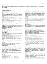
The temperature in this manual is expressed by Centigrade.If Fahrenheit is used, the switchover between them is 

Tf=TcX1.8+32.

1.Temperature Parameters

Indoor preset temperature (Tpreset)

Indoor ambient temperature (Tamb.)

2.Basic Functions

Once the compressor is energized, there should be a minimum 

interval of 3 minutes between two start-ups. Once the compressor 

operates, the unitwill not stop within 6 minutes due to temperature 

change.

1)Cool Mode

(a) When Tamb.≥1°C(2°F), the unit starts cooling 

operation. In this case, the compressor and motor operate and the 

fanoperates at set speed. 

(b) When Tamb.≤Tpreset-1°C(2°F), the compressor and the motor 

stop while the fan runs at set speed.

(c) When Tpreset-1°C(2°F)<Tamb.<1°C(2°F), the unit 

willmaintain its current running status. In cooling mode, temperature 

setting range is 16~30°C(61~86°F).

2)Dry Mode

In this mode, the set temperature and ambient temperature will not 

be displayed. Fan will operate at low speed while compressor , fan 

and motor continuously operate.

3)Fan Mode

In fan mode, set temperature and ambient temperature will not 

be displayed. Fan will operate at set speedwhile compressor and 

motor stop operating.In this mode, temperature setting range is 

16~30°C(61~86°F).

4)AUTO Mode

In AUTO mode, Tpreset in standard cooling is 25°C(77°F) while in 

standard heating is 20°C(68°F).

When Tamb.26°C>(79°F), the unit enters auto cooling mode;When 

Tamb.20°C<(68°F), the unit enters auto fan mode;

When 20°C(68°F)≤Tamb.≤23°C(73°F) if the unit is in fan mode, it 

will keep its status; If not, it will enter auto dry mode; 

When 26°C(79°F)≥Tamb.≥24°C(74°F), the unit enters auto dry 

mode;

When 26°C(79°F)≥Tamb.≥20°C(74°F), If the unit is energized for 

the first time, it will enter dry mode.

3.Basic Functions

1)Buzzer

Upon energization or availably operating the unit or remote 

controller, the buzzer will give out a beep.

2)Sleep Function

(a) After setting the sleep function in cooling mode, Tpreset will 

increase1°C(2°F) in 1 hour later and 2°C(4°F) to tally in 2 hours 

later.After that, the set temperature will not increase any more and 

the upper limit of set temperature after increase is 30°C(86°F).

(b)There is no sleep function in Fan or Dry mode.

(c)After setting sleep function, it will be cancelled by switching 

operation mode. 

(d)The set temperature displayed on remote controller will not 

change with the decrease or increaseof the set temperature in this 

mode.

3)Auto Fan

(a)fan speed in cooling mode: 

Tamb.≥T 2°C(4°F),                  High speed; 

Tpreset<Tamb.<T2°C(4°F),     Medium speed; 

Tamb.≤Tpreset,                                     Low speed;

(b) There is 210s’ delay for switch of Auto Fan mode.

4)Timer function

General Timer

Timer ON can be set at unit OFF. If selected ON time is reached, 

the unit will start to operate according to previous setting status. 

Time setting range is 0.5-24hr in 30-minute increments.Timer OFF 

can be set at unit ON. If selected OFF time is reached, the unit 

will stop operation. Time setting range is 0.5-24hr in30-minute 

increments.

Clock Timer 

Timer ON

If timer ON is set during operation of the unit,the unit will continue 

to operate. If timer ON is set at unit OFF, upon ON time reaches the 

unit will start to operate according to previous setting status.

Timer OFF 

If timer OFF is set at unit OFF, the system will keep stand by status. 

If timer OFF is set at unit ON, upon OFF time reaches the unit will 

stop operation.

5)Memory Function

If the unit is de-energized, it will operate at the previous mode after 

it is energizedagain. If the unit operates before de-energization,the 

compressor will operate in 3 min later after the unit is energized 

again.

6)Indicator Lamp and “Dual 8” Nixie Tube

(a)When the unit operates at cooling mode, the cooling indicator 

lamp is on and “dual 8”nixie tube displays set temperature.

(b)When the unit operates at fan mode, the fan indicator lamp is on 

and“dual 8”nixie tube will not display anything.

(c)When the unit operates at dry mode, the dry indicator lamp is on 

and “dual 8”nixie tube will not display anything.

7)Button

(a) ON/OFF :control ON/OFF of the unit

(b) Mode: The setting of mode is circulated as the cooling mode

Dry mode

Fan mode. 

(c)/: Press “+” to increase the set temperature while press “-” to 

decrease the set temperature when the unit operates.The set 

temperature will increase or decrease 1°C or 1°F for each press. 

The set temperature can’t be decreased if it reaches 16°C or 61°F 

while it can’t be increased when it reaches 30°C or 86°F. In that 

case, Auto, Dry or Fan mode will be invalid.

(d) Fan: Fan speed setting circulated as following: low-medium-

high-auto-low.

8)Light Control

If light is turned on by remote control, the indicator lamp and “dual 8” 

nixie tube will display the current status. If it is turned off, all lights 

will be turned off. If the button on front panel or remote controller 

is pressed when the light is turned off, the indicator lamp and “dual 

8”nixie tube will display the current status for 5s and then the light 

will be turned off. The display of malfunction is not affected by 

remote light control.

4.Protection Function

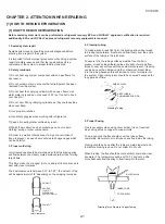
1)Freeze Prevention Protection

When the freeze prevention protection is detected, the compressor 

will stop and the fan will operate at set speed. Once such protection 

is removed, the previous status will be resumed in 3 minutes later.

2)Overflow Prevention Protection

When detecting that the water is full for continuous 3 seconds, 

overflow prevention protection will occur, malfunction code H8 will 

be displayed.

Summary of Contents for CV10CTXB

Page 1: ...ARTS 1 1 3 WIRING DIAGRAM 1 2 4 EXTERNAL DIMENSION 1 3 5 PART NAMES 1 4 CHAPTER 2 ATTENTION WHEN REPAIRING 1 HOW TO REPAIR REFRIGERATION 2 1 CHAPTER 3 TROUBLESHOOTING GUIDE 1 TROUBLESHOOTING 3 1 2 FUNCTION 3 4 CHAPTER 4 DISASSEMBLING PROCEDURE 1 DISASSEMBLING PROCEDURE 4 1 Parts Guide CONTENTS PORTABLE AIR CONDITIONER CV 10CTX W CV 10CTX B CV 10CTX S MODEL In the interests of user safety Required ...

Page 2: ...ctrical Data Type Hermetically sealed rotary type Model Motor Output YZG A082Y2D2 850W Compressor Evaporator Aluminum Fin copper Tube Condenser Aluminum Fin copper Tube Control O D x I D x Length mm Φ2 3 x Φ1 0 x 450 Capillary Charge Refrigerant Volume R 410A OZ 16 9 REFRIGERANT SYSTEM Width Height Depth Inch mm 13 4 340 x 30 7 780 x 15 5 394 Net Weight Lbs 53 NET DIMENSIONS Width Height Depth Inc...

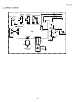
Page 3: ...EGN M2 WATER MOTOR 17 RT1 AP2 DISP1 ROOM TEMP DISP2 RD W7 W6 HIGH WP BK WH COM NC SA BU W1 COMP MOTOR DISP1 BU WH BK YE RD W4 FAN RD W2 DISP2 WATER WATER1 N1 AP1 R M V COMP 4 L 3 K201 C1 YE W3 1 2 C T U YEGN COMP S W X W5 N3 BU BU WH YEGN GN N BN BK L POWER ROOM WATER LEVEL SWITCH SAT TUBE TUBE TEMP RT2 SENSOR ...

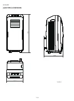
Page 4: ...1 3 CV10CTX 4 EXTERNAL DIMENSION Unit inch High Min Low Auto FAN SPEED ON OFF Fan only Heat Dry Cool MODE High Min Low Auto FAN SPEED ON OFF Fan only Heat Dry Cool MODE 13 4 30 7 15 5 ...

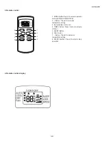
Page 5: ...s it to increase temperature setting 3 Not available on this unit 4 TIMER Button Press it set auto on auto off timer 5 SLEEP Button 6 FAN Button 7 Button Press it to decrease temperature setting 8 ON OFF Button Press it to start or stop operation ON OFF MODE FAN SLEEP TIMER AUTO COOL DRY FAN T ONT OFF SLEEP LOCK SPEED 1 2 3 4 5 6 7 8 ...

Page 6: ...r view 1 Control panel and display lamp 2 Remote control signal receiver window 3 Handel 4 Remote controller box 5 Air outlet 6 Vertical louvers 7 Horizontal louvers 8 Wheel 9 Air inlet 10 Grille 11 Air outlet 12 Air inlet 13 Power cord hook 14 Power cord 15 Rear clip bottom 16 Rain guard 17 Mothproof net 18 Rear clip upper 19 Exhaust hose 20 Joint 21 Remote Controller ...

Page 7: ...flow between the closely mated surfaces rather than forming large fillets This films make the strongest joints capillary attraction also work best with close tolerance The best clearance is between 0 01 to 0 03 the amount of lap will be approximately 3 8 depending on the swaging tool used 4 Cleaning tubing To make a sound leak tight joint the brazing alloy when raised to brazing temperature must w...

Page 8: ... that the boiling point of any water in the system will be lowered to a point where it will vaporize and be expelled from the system in the form of vapor 7 1 Type of evacuation methods 1 Piston Type Compressor No good System parts must be above 110 F 2 Rotary Vacuum Pump Disavantages Low CFMC 4 oil gets dirty 3 Single State Vacuum Pump will not clean oil Oil must be changed often 4 Two Stage Vacuu...

Page 9: ... system After the diagnosis has been made they must be removed so that the system will be restored to a hermeticly sealed condition RUNNING CAPACITOR AND FAN CAPACITOR NOTE DISCHARGE THE RUNNING CAPACITOR AND FAN CAPACITOR BEFORE TOUCHING CAPACITOR OR WIRING 1 Discharge capacitor by shorting terminals 2 Take the wires off the capacitor terminals 3 Set the selector switch of a volt ohm meter or a t...

Page 10: ...us Is malfunction eliminated Is malfunction eliminated Replace main board of indoor unit Replace temperature sensor Is malfunction eliminated Replace main board of outdoor unit Energize and turn on the unit yes yes yes yes no no no no no no no Adjust the connection status 1 Failure for Temperature Sensor Main test point If the outdoor environment temperature is in normal range If fan motor normall...

Page 11: ...the water of chassis Connection line of water level switch is tight Failure is cancelled Adjust connection Failure is cancelled Replace the switch of water level Failure is cancelled Replace control board End Main test point If the defrosting tray is over blow If the connection line of water level switch is good If the water level switch is damaged Check the flow process of failure is ...

Page 12: ... abnormally Is there abnormal sound or oil leakage is the temperature of the shell too high etc no no no no yes no no Replace the control panel End Normal fluctuation is within 10 of the rated voltage on the nameplate yes Malfunction is eliminated no Adjust the supply voltage to maintain it within normal range yes Malfunction is eliminated no Clean the indoor and outdoor heat exchangers and remove...

Page 13: ...nction General Timer Timer ON can be set at unit OFF If selected ON time is reached the unit will start to operate according to previous setting status Time setting range is 0 5 24hr in 30 minute increments Timer OFF can be set at unit ON If selected OFF time is reached the unit will stop operation Time setting range is 0 5 24hr in30 minute increments Clock Timer Timer ON If timer ON is set during...

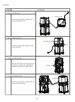
Page 14: ...ION MANUAL DRAINAGE SHOULD BE PERFORMED BEFORE ANY SERVICE SEE WHENEVER THE UNIT IS MOVED OF OPERATION MANUAL 1 Remove the panel sub assy panel sub assy 2 Remove cable collection board cable collection board 3 Remove grille and filter sub assy grille and filter sub assy Steps Procedure Remove the two screws fixing panel sub assy lift to remove the panel sub assy Remove the screws fixing cable coll...

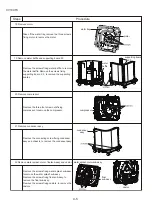
Page 15: ... the six screws fixing rear board to remove the rear board assy Remove the screws fixing the left right and back side of the front panel to remove the panel sub assy Remove the fixing screws fixing display board sub assy to remove the display board sub assy Remove the two screws fixing electric box cover to remove the electric box cover Pull off the connection cable on electric box remove the scre...

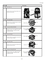
Page 16: ...y evaporator Steps Procedure Remove the screws fixing propeller cover to remove the propeller cover Remove the screw fixing supporting board to remove the board1 Welding cut the joints on the connection pipe to remove the connection pipe Discharge the refrigerant clearly before welding cutting Remove the screws fixing evaporator assy to remove the evaporator assy ...

Page 17: ...edure Remove the four screws fixing air flue assy to remove the air flue assy Remove the four screws fixing upper propeller to remove the upper propeller Remove the screw nut and gasket fixing upper centrifugal fan blade to remove the upper centrifugal fan blade Remove the three screws fixing lower propeller to remove the lower propeller Remove the four screws fixing air guide loop to remove the d...

Page 18: ...e screws fixing motor to remove the motor Remove the screws fixing water baffle to remove the water baffle Remove the screws fixing supporting board 2 3 to remove the supporting boards Remove the three foot screw nuts fixing compressor to remove the compressor Remove the connecting screw fixing condenser assy and chassis to remove the condenser assy Remove the screws fixing water splash sub assy t...

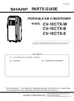
Page 19: ...ales service only The contents are subject to change without notice CV10CTX PORTABLE AIR CONDITIONER CV 10CTX W CV 10CTX B CV 10CTX S MODEL In the interests of user safety Required by safety regulations in some countries the set should be restored to its original condition and only parts identical to those specified should be used 1 CV 10CTX W CV 10CTX B CV 10CTX S 2 PACKAGE 3 SUPPLIED ACCESSORIES...

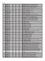
Page 20: ...0CTX B 6 9JQ2000611602 Front Case CV 10CTX W 6 9JQ27220105240 Front Case CV 10CTX B 6 9JQ2000611602P Front Case CV 10CTX S 7 9JQ30567022 Display Board CV 10CTX W CV 10CTX B CV 10CTX S 8 9JQ63066061 Membrane CV 10CTX W 8 9JQ63026168 Membrane CV 10CTX B CV 10CTX S 9 9JQ03006269 Capillary Sub assy CV 10CTX W CV 10CTX S 9 9JQ3006168 Capillary Sub assy CV 10CTX B 10 9JQ01006098 Evaporator Assy CV 10CTX...

Page 21: ...V 10CTX S 37 9JQ20186188 Water Retaining Box CV 10CTX W CV 10CTX B CV 10CTX S 38 9JQ2012612202 Cover of Remote Control Box CV 10CTX W 38 9JQ2012612205 Cover of Remote Control Box CV 10CTX B 38 9JQ20126122 Cover of Remote Control Box CV 10CTX S 39 9JQ2011603602 Remote Control Box CV 10CTX W 39 9JQ2011603605 Remote Control Box CV 10CTX B 39 9JQ20116036 Remote Control Box CV 10CTX S 40 9JQ2611612502 ...

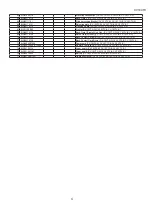
Page 22: ...ind Pipe CV 10CTX W CV 10CTX B CV 10CTX S 69 9JQ26116120 Baffle Plate Air vent CV 10CTX W CV 10CTX B CV 10CTX S 70 9JQ26116132 Back Contact Card Up CV 10CTX W CV 10CTX B CV 10CTX S 71 9JQ26116135 Back Contact Card Down CV 10CTX W CV 10CTX B CV 10CTX S 72 9JQ4002087906 Power cord CV 10CTX W CV 10CTX B CV 10CTX S 73 9JQ30510092_K75948 Remote Controller CV 10CTX W CV 10CTX B CV 10CTX S 74 9JQ12126114...

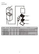
Page 23: ...kaging Foam CV 10CTX W CV 10CTX B CV 10CTX S 80 9JQ51086105 Package Cushion CV 10CTX W CV 10CTX B CV 10CTX S 81 9JQ51066125 Packaging Accessories CV 10CTX W CV 10CTX B CV 10CTX S 82 9JQ63229939004 Inside Carton Box CV 10CTX W 82 9JQ63229939005 Inside Carton Box CV 10CTX B 82 9JQ63229939006 Inside Carton Box CV 10CTX S 83 9JQ51029930611 Over pack Carton CV 10CTX W CV 10CTX B CV 10CTX S ...

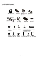
Page 24: ... 9JQ03616154 Rain guard 2 9JQ26116119 Bracket 9JQ02111151 Power cord hook 2 9JQ7101600502 CV 10CTX W 9JQ7101600505 CV 10CTX B 9JQ71016005 CV 10CTX S Drain hose 9JQ05230013 Screw 2 9JQ70140554 Foam seal B adhesive 9JQ121261141 Hose Clamp 9JQ261160383 Hose clip 2 9JQ70810222 Rubber plug 9JQ06816101 Remote control 9JQ30510092_K75948 Battery 2 AAA 1 5A 9JQ49010055 Manual 9JQ66129911007 Insect guard ne...

Page 25: ...ED No part of this publication may be reproduced stored in a retrieval system or transmitted in any form or by any means electronic mechanical 23 5 7 嘋 6 53 25325 7 21 ALL RIGHTS RESERVED COPYRIGHT 2011 BY SHARP CORPORATION ALL RIGHTS RESERVED No part of this publication may be reproduced stored in retrieval systems or transmitted in any form or by any means electronic mechanical photocopying re c...

Reviews: