<Adjustment specification>
Mode
Specification
SIM
Set value
Set range
Original off
center mode
(OC mode)
Single:
Center
±
2.0 mm
SIM
50-13
Add 1:
0.1 mm shift
to R side
Reduce 1:
0.1 mm shift
to L side
1
∼
99
Duplex:
Center
±
2.5
mm
b. SPF mode
Note:
●
Before performing this adjustment, be sure to check that the
paper off center is properly adjusted.
1) Make a test chart for the center position adjustment and set it on
the SPF.
<Adjustment specification>
Draw a line on a paper in the scanning direction.
2) Make a normal copy from the manual paper feed tray, and com-
pare the copy and the original test chart.
If necessary, perform the following adjustment procedures.
3) Execute SIM 50-16.
4) After warmup, shading is performed and the current set value of
the off center adjustment at each paper feed port is displayed on
the display section in 2 digits.
5) Enter the set value and press the start key.
The set value is stored and a copy is made.
<Adjustment specification>
Mode
Specification
SIM
Set value
Set range
Original off
center mode
(SPF mode)
Single:
Center
±
3.0 mm
SIM
50-16
Add 1:
0.1 mm shift
to R side
Reduce 1:
0.1 mm shift
to L side
1
∼
99
Duplex:
Center
±
3.5
mm
(8) OC (SPF) open/close detection position adjustment
1) Set A4 or 8 1/2"
×
11" paper on the OC table.
Check that the document size display on the operation panel in-
dicates the correct size of the set paper.
2) Close the OC (SPF) with a small clearance for insertion of your
hand left, and remove the paper from the OC table.
The document size display does not change from the display in 1).
3) Open the OC (SPF) slowly until the display on the operation panel
changes (all the document size display lamps are turned off), and
measure dimension A shown below under that state.
<Spec value>
OC (SPF) open/close position A: 207
∼
302mm
4) If the OC (SPF) open/close position A is not 207
∼
302mm, adjust
the open/close sensor mounting plate position as shown below.
(9) Original sensor adjustment (SIM 43-3)
1) Execute SIM 41-2.
2) Set A3 (11"
×
17") paper on the OC table.
3) Press the start key again.
4) The sensor level of the original sensor is automatically checked
and the value with an original - 40 is made as the threshold value
for scanning. (Automatic setting)
5) Execute SIM 43-3.
6) The light reception level of the original sensor is displayed.
The first digit of the copy quantity display shows “A”: Light recep-
tion level display
The first digit of the copy quantity display shows “b”: Original
judgement level display
(The mode selection is made with the magnification ratio display
key.)
7) By changing the paper set on the original table, the original size
LED sensed by the sensor is lighted.
C. Image density adjustment
(1) Copy mode (SIM 46-1)
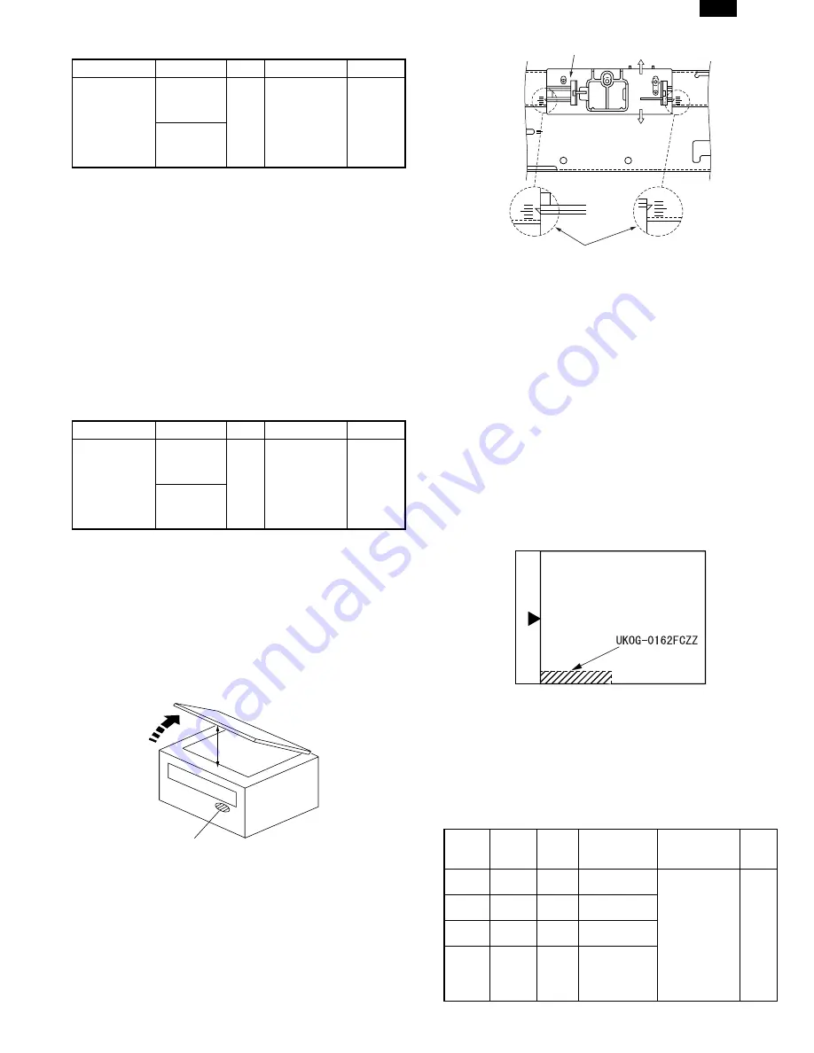
1) Set a test chart (UKOG-0162FCZZ) on the OC table as shown
below.
2) Put several sheets of A3 or 11"
×
17" white paper on the test
chart.
3) Execute SIM 46-1.
4) After warmup, shading is performed and the current set value of
the density level is displayed on the display section in 2 digits.
For mode selection, use the density select key.
5) Change the set value with the 10-key to adjust the copy image
density.
6) Make a copy and check that the specification below is satisfied.
<Adjustment specification>
Den-
sity
mode
Dis-
play
lamp
Ex-
posure
level
Sharp Gray
Chart output
Set value
Set
range
Auto
Auto
—
“3” is slightly
copied.
The greater
the set value
is, the
greater the
density is.
The smaller
the set value
is, the
smaller the
density is.
1
∼
99
Manual
Manual
3
“3” is slightly
copied.
Photo
Photo
3
“3” is slightly
copied.
Toner
save
Manual
/
Photo
3
“3” is slightly
copied.
Open
A
Distance A = Table glass top - OC (SPF) knob 117"
Check the position where the display checked in
procedure 1) is changed.
(A)
(B)
Open/close sensor mounting plate
Factory setting : second from the top
DM-2000
6 – 8


