background image

Serial Dot Matrix
Printer 

MODEL

DP-750

CHAPTER 1. Printer Handling and Maintenance ............................................. 1

CHAPTER 2. Specifications and Operation Principles ..................................... 2

CHAPTER 3. Disassembly and Assembly ..................................................... 10

CHAPTER 4. Troubleshooting........................................................................ 29

PARTS GUIDE (PRINTER ASSEMBLY : KI-OB2014RC01)

APPLICATION MODEL : UP-600 ("U" & "A" version)

CONTENTS

Parts marked with "

" are important for maintaining the safety of the set. Be sure to replace these parts with specified

ones for maintaining the safety and performance of the set.

SHARP CORPORATION

This document has been published to be used 
for after sales service only.
The contents are subject to change without notice.

   SERVICE MANUAL

Summary of Contents for DP-750

Page 1: ...UIDE PRINTER ASSEMBLY KI OB2014RC01 APPLICATION MODEL UP 600 U A version CONTENTS Parts marked with are important for maintaining the safety of the set Be sure to replace these parts with specified ones for maintaining the safety and performance of the set SHARP CORPORATION This document has been published to be used for after sales service only The contents are subject to change without notice SE...

Page 2: ...urnal near end sensor CONTENTS Symbol PartsCod CHAPTER 1 Printer Handling and Maintenance 1 CHAPTER 2 Specifications and Operation Principles 2 2 1 General Specifications 2 2 2 Mechanism Outline 4 2 3 Mechanism and Operation Principles 4 2 3 1 Drive Force Transmission Assembly 4 2 3 2 Sensor Assembly 4 2 3 3 Print Head Assembly 5 2 3 4 Paper Feed Assembly 6 2 3 5 Ribbon Cassette Assembly 6 2 3 6 P...

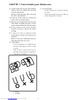
Page 3: ... 5 If the print head is powered while condensation is present the head may be destroyed Make sure that any condensation has been fully dried before starting to print 6 Loading paper Cut the tip of the paper in a straight line and make sure that the paper is not frayed folded or creased When the paper emerges from above the print head grasp it and pull it out slightly to verify that it is set strai...

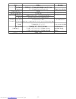
Page 4: ...0 V DC m10 34 ohms m10 at 25 C 24 0 V DC m10 8 25 ohms m10 at 25 C DC brush motor 24 0 V DC m10 Approx 1 6 A Approx 250 mA CHAPTER 2 Specifications and Operation Principles 2 1 General Specifications Rating Remarks Item 24 0 V DC 25 C continuous printing Character spacing 2 positions Option At startup with 24 0 V DC 25 C During continuous printing with 24 0 V DC 25 C Total number of dots Basic cha...

Page 5: ...ines 100 million characters 2 million dots pin Temperature 0 to 50 C Humidity 10 90 RH above 39 C equivalent to 40 C 85 RH Temperature 25 to 70 C Humidity 40 C 90 RH 96 hours 150 W x 230 3 D x 150 7 H mm Type A 150 W x 234 6 D x 123 7 H mm Type B Approx 1180 g No condensation To be stored with ribbon cartridge removed Including take up device Mechanism Head Operation environment Storage environmen...

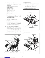
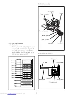
Page 6: ...me Motor assembly For information on peripheral circuitry connected to this printer please refer to the respective documentation 2 3 Mechanism and Operation Principles This section explains the construction and operation of 8 out of the 10 blocks listed above excluding the frame and motor assembly 2 3 1 Drive Force Transmission Assembly The drive force of the motor assembly is transmitted to the v...

Page 7: ...ome position sensor HP dot pulse sensor DP and reset pulse sensor RP Powered DP Dot pulse sensor RP Reset pulse sensor Powered Powered Powered Powered Powered Powered Powered Powered HP Home position sensor Print head Print solenoid 1 Print solenoid 2 Print solenoid 3 Print solenoid 4 Print solenoid 5 Print solenoid 6 Print solenoid 7 Print solenoid 8 Print solenoid 9 2 Head drive assembly 3 Print...

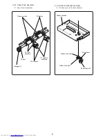
Page 8: ...embly PF gear Idling gear 2 PF latches Pressure rollers 2 3 4 Paper Feed Assembly 1 Paper feed mechanism Ribbon cassette Ribbon drive shaft Worm wheel Reduction gear 1 Ribbon drive gear 2 3 5 Ribbon Cassette Assembly 1 Ribbon cassette feed mechanism ...

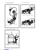
Page 9: ...ke up mechanism 2 Near end detection mechanism 3 Take up mechanism types Type which is the same height as the main unit Type which is lower than the height of the main unit Microswitch Roll paper End switch lever Switch holder Roll paper core hole center when diameter is large Roll paper core hole center when diameter is small ...

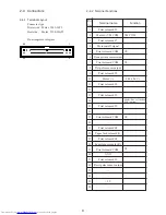
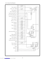
Page 10: ...OM Dot pulse sensor output Print solenoid 5 Motor Print solenoid 2 Print solenoid 1 Print solenoid 9 Print solenoid COM Print solenoid 8 Paper feed solenoid J Print solenoid 4 Paper feed solenoid R Print solenoid COM GND Print solenoid 6 Reset pulse sensor output 5 V VM COM VS VS VM 24 V Multi line validation SOL option VS VS 2 4 Connectors 2 4 1 Terminal Layout Connector type Printer side Molex 5...

Page 11: ...ion pulse Print solenoid COM VS D P dot pulse Print solenoid 5 Motor 24 V Print solenoid 2 reserved Print solenoid 1 reserved Print solenoid 9 reserved Print solenoid COM VS Print solenoid 8 Paper feed solenoid J Print solenoid 4 Paper feed solenoid R Print solenoid COM VS GND Print solenoid 6 RP reset pulse Blank Blank Blank Blank RP 5 V ...

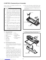
Page 12: ...sumes that the individual assemblies are complete For information on the procedures for individual assemblies please refer to Section 5 Parts List The part names used in the explanatory text are those indicated in Section 5 Parts Lists These part names are used commonly throughout this service manual 2 Fit pressure roller springs L and R onto both sides of PF housing and set platen assembly in pla...

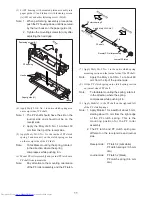
Page 13: ...t Note To facilitate mounting the spring rotate it in the direction where the spring compresses while pushing it in 6 Mount PF roller assembly and journal PF latch onto PF shaft from journal side Note Pay attention to the mounting orientation of the PF roller assembly and the PF latch 7 Apply Moly LG S No 1 to the entire clutch spring mounting section on the journal side of the PF shaft Note Apply...

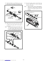
Page 14: ...g Apply Moly LG S No 1 to outer circumference PF clutch spring 2 Apply Moly LG S No 1 to outer circumference Receipt side PF latch 2 PF latch 5mm 5mm Apply Mobile 1 10mm 5mm 10mm 5mm 12 Insert the PF shaft assembly into the PF housing and apply ORELUBE G 1 3 to the left and right fixing lever L and R Note When mounting the PF shaft assembly match the PF roller assembly and PF latch position to the...

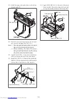
Page 15: ...ixing lever spring to fixing levers L and R 15 Insert the paper guide spring into pressure roller shaft assembly Note Pressure roller shaft assembly refers to the pressure roller shaft with mounted pressure rollers 16 While pushing the pressure roller springs L and R towards the front side mount the pressure roller shaft assembly in the PF housing Note After mounting verify that the pressure rolle...

Page 16: ... to the pivot of the spool holder assembly Fit the spool gear assembly with the mounted winder pulley in and fasten it with E ring E3 Pivot Apply Moly LG S No 1 Apply Moly LG S No 1 Winder pulley Spool spring Spool gear assembly Washer Spool holder assembly E ring 23 Apply ORELUBE G 1 3 to the pivot of the main frame assembly Mount the carriage drive gear and carriage drive pulley and fasten with ...

Page 17: ... displacement must be 2 mm 28 Apply ORELUBE G 1 3 to the fastening boss of the stamp lever plate in the paper guide L assembly and to the three slits contacting the plate Note Paper guide L assembly refers to the paper guide L with pressure rollers paper pressure sheet 1 line validation PCB assembly and validation guide plate installed 29 Install the paper guide L assembly in the main frame assemb...

Page 18: ...s on the right side of the main frame assembly 32 Mount the motor gear on the shaft of the motor assembly 33 Install the bevel gear 1 and fasten with E ring E2 over the bevel gear 1 pivot Rear Pivot Apply ORELUBE G 1 3 Main frame assembly 30 Mount the motor assembly and motor spacer on to the right side of the main frame assembly and fasten with fastening screws M3x5 Note Mount the motor so that t...

Page 19: ...nstall Note Bevel gear 2 assembly refers to reduction gear 3 with installed bevel gear 2 38 Mount the reduction gear 2 39 Install the reduction gear 1 and slide washer and fasten with E ring E2 40 Install the rear cushion Note Install the rear cushion from the side opposite the slit Frame R support plate assembly Rear cushion Reduction gear 4 Reduction gear 2 Reduction gear 1 Washer E ring Bevel g...

Page 20: ...unting position on the frame R support plate assembly 46 Mount E ring E2 on to the worm wheel pivot 47 Apply EPINOC AP 1 to the worm wheel pivot 48 Insert the worm wheel pivot from the hole in the bottom of the main frame assembly and install in the worm wheel assembly 49 Push the worm wheel pivot into the hole of the ribbon pivot bushing and fit the bushing into the frame R support plateassembly ...

Page 21: ...gh the rectangular cutout in the PCB to the bottom side 3 Take care that the ceramic condenser and transistor on the PCB around dot pulse sensor do not come into contact with the motor assembly timing disc 56 Mount the FFC fixer plate on the main PCB assembly and fasten with fastening screw M3x6 52 Note 1 Moisten the felt with Mobile 1 2 When installing start from a position where the carriage dri...

Page 22: ...tor Ceramic condenser Soldering holes FFC fixer plate Nut 57 Place the insulating sheet and transistor on the main PCB assembly and fasten with the fastening screw M3x10 Note When installing bend the transistor legs at a right angle in alignment with the soldering holes on PCB 58 Screw the nut M3 on to the fastening screw M3x10 and fasten the FFC fixer plate ...

Page 23: ...ead cable Slit Carriage 64 Install the ribbon plate assembly in the main frame assembly and fasten with the fastening screws M3x5 Note 1 Ribbon plate assembly refers to the ribbon plate with blind label and ribbon cassette cushion 2 When installing engage the protrusion on the ribbon plate assembly in the mount hole on the main frame assembly and then slide the assembly to the right Rear Main fram...

Page 24: ...aft Positioning slit Rear Bent tip Apply EPINOC AP 1 Protrusion Apply EPINOC AP 1 67 Mount the manual cutter on the 2 station housing cover 2 station housing cover Manual cutter 65 Insert the ribbon plate spring in the ribbon plate assembly and the main frame assembly front center 66 Mount the head cover on the main frame assembly and fasten with fastening screws M3x5 Note While installing the PF ...

Page 25: ... order 1 Print speed adjustment 2 Platen head gap adjustment 3 Bidirectional printing shift adjustment 4 Reset pulse RP home position HP waveform check 3 4 1 Print Speed Adjustment 1 Procedure Perform the bi directional printing and use an oscilloscope to measure cycle A of the reset pulse RP 2 Check points RP waveform Connector pin 26 GND Connector pin 24 Note Perform the adjustment under the fol...

Page 26: ... locations right left center 2 Retighten the loosened screws Gap Adjustment procedure 0 5 0 55 mm When gap is out of range Adjust the gap by turning two adjustment screws on rear Main PCB assembly Validation sensor adjustment VR Print speed adjustment VR 3 4 3 Bi directional Printing Shift Adjustment 1 Procedure Perform bidirectional printing Judge the results and rotate the motor shaft while hold...

Page 27: ...nal printing and use an oscilloscope to measure the phase shift A between the reset pulse RP waveform and home position pulse HP waveform 2 Check points RP waveform Connector pin 26 HP waveform Connector pin 6 GND Connector pin 24 3 Adjustment Verify that the value of A is between 3 and 8 ms ...

Page 28: ...crews M3x5 and remove the head cover 5 Move the ribbon plate as follows 1 Remove the ribbon plate fastening screw M3x5 2 Raise the ribbon plate rear side and slide to left 3 Raise the ribbon plate front and disengage from the main frame assembly protrusion 4 Raise the ribbon plate and rotate counterclockwise around the ribbon drive shaft until the head cable is visible Note Because the ribbon plat...

Page 29: ... assembly Cable fixing sheet Head cable Head cable Slit Carriage Protrusion 3 5 2 Assembly Procedure 1 Plug the head cable into the head assembly connector Note Make sure that the head cable is pushed fully into the connector 2 Insert the head assembly into the carriage guide Just before the assembly is fully seated push the bent section of the head cable into the carriage slit Note Take care not ...

Page 30: ...e of the main frame assembly 8 Open the PF housing assembly 9 Insert the ribbon cassette 10 Mount the printer in the POS ECR system 6 Install the head cover Note When installing make sure that the head cover left right positioning part and the main frame assembly left right protrusion are fully matched 7 Fasten the head cover with 2 screws Rear Ribbon plate spring Ribbon plate Fastening screw Ribb...

Page 31: ...blem with voltage applied to motor M a i n P C B a s s e m b l y is defective Paper jam Paper is jammed with ink ribbon or print head wire Foreign object in gear wheel train or gear is damaged Head movement problem 4 1 Repair Procedure When a problem has occurred check the symptoms carefully and use the instruction in the section 4 2 Repair Steps to isolate the problem When the cause is found repa...

Page 32: ... is supplied Observe waveform of signal at pin 6 HP pin 8 DP and pin 26 RP and check whether signal is normal If there is a phase shift reseat the time belt assembly L u b r i c a t e i f n o t s u f f i c i e n t l y lubricated If not supplied repair the printer control section If signal is not normal replace the main PCB assembly If there is a problem repair the printer control section or replac...

Page 33: ...nob rotation and take up action of the ribbon Turn motor gear clockwise by hand and check whether gear train moves Check gap between print head and platen Check voltage and continuity of print solenoid voltage supplied by printer control section Check whether shift disappears when rotating timing disk while holding motor shaft Check whether paper tip is folded or not properly cut Check whether pap...

Page 34: ...maged gear Check whether the PF slip mechanism has enough force for paper feed Check the PF latch for wear Check whether ribbon cassette is inserted correctly Turn ribbon cassette take up knob in arrow direction and check knob rotation and take up action of the ribbon Turn motor gear clockwise by hand and check whether the gear train moves If there is a problem repair the printer control section o...

Page 35: ...74 0 C Z N E 3 2 0 0 1 0 AL C Pivot Wheel Worm 75 0 C Z N E 3 2 2 0 1 0 AH C Shaft Drive Ribbon 76 0 C Z N E 3 4 1 0 2 1 AN C Plate Ribbon 79 0 C Z N E 4 3 6 0 1 0 AG C Spring Plate Ribbon 81 0 C Z N E 4 4 1 0 8 1 AP D Cover Head 84 0 C Z N E 6 6 7 0 1 1 BH E SA PWB Main 87 0 C Z C 7 8 0 2 0 2 9 AH C Insulating sheet S 16 88 0 C Z E 0 0 7 3 0 0 5 AD C Screw PH SW M3 5 89 0 C Z N E 2 2 0 0 5 0 AK C...

Page 36: ...29 32 66 116 117 118 104 52 41 8 71 41 39 38 27 37 9 28 26 114 107 90 73 75 90 74 72 5 5 3 10 115 128 129 90 21 90 24 89 88 101 3 842 100 84 841 87 102 1 31 33 109 79 2 220 110 34 110 2 2 108 119 105 76 81 106 23 10 2 112 113 22 22 111 103 DP 750 2 ...

Page 37: ...2 4 1 0 3 1 AH C Armature PF 58 0 C Z N E 2 4 1 1 2 0 AH C Cutter Manual 59 0 C Z N E 2 4 1 1 3 0 AS C Plate Guide Validation 61 0 C Z N E 2 4 2 0 2 1 AS C Guide Paper Pull 64 0 C Z N E 2 4 2 0 5 1 AW C Guide U paper 65 0 C Z N E 2 4 2 0 6 1 AH C Plate Guide Paper Side 68 0 C Z N E 2 4 7 0 1 1 AS C SA Platen 70 0 C Z N E 2 5 7 0 1 1 AX B SA Solenoid PF 78 0 C Z N E 4 3 1 0 1 0 AG C Spring Earth 82...

Page 38: ...ism etc No 2 RCP003901 55 59 82 86 4 4 65 65 65 6 7 64 7 6 49 8 45 8 43 61 45 8 8 9 125 56 51 96 702 5 130 51 3 56 96 120 5 70 5 3 78 51 97 53 48 68 122 123 47 5 58 126 5 121 46 50 47 124 40 9 127 701 DP 750 4 ...

Page 39: ...storedinaretrievalsystem ortransmitted Inanyformorbyanymeans electronic mechanical photocopying recording orotherwise withoutpriorwrittenpermissionofthepublisher SHARP CORPORATION Digital Document Systems Group Quality Reliability Control Center Yamatokoriyama Nara 639 1186 Japan 2001 May Printed in Japan ...

Reviews: