10
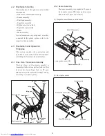
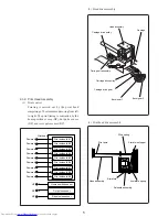
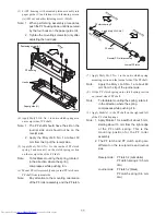
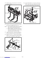
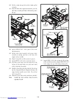
Rear
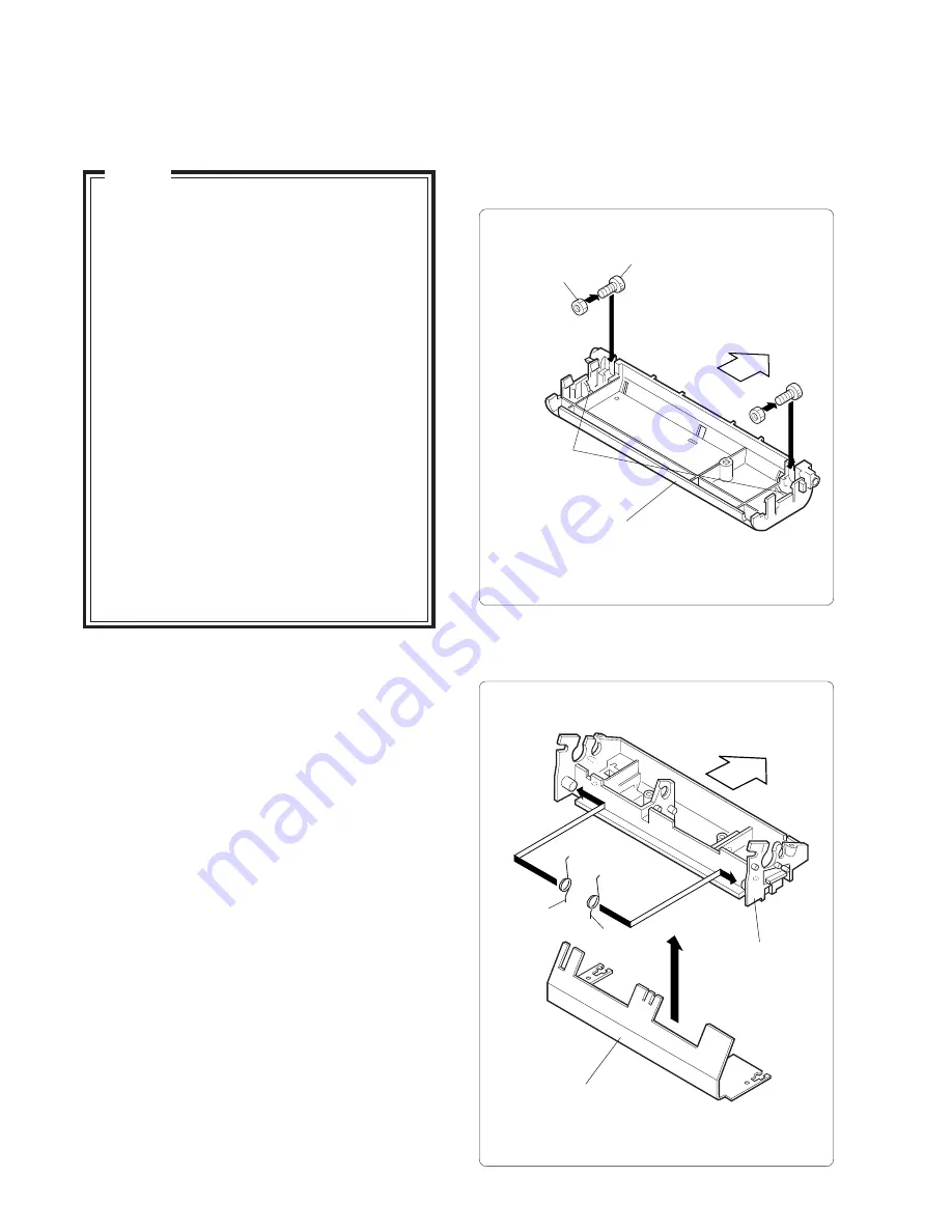
PF housing
Pressure roller
spring (L)
Pressure roller
spring (R)
Platen assembly
Rear
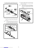
Fastening screw
Nut
Paper guides (U)
V-shaped cutout
CHAPTER 3. Disassembly and Assembly
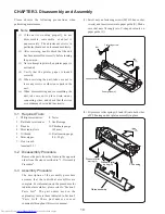
(1) Screw nuts on fastening screws (M3x10 hex socket
screws) and insert screws into paper guide (U). Make
sure that nuts fit snugly into V-shaped cutouts on
paper guide (U).
Please observe the following precautions when
performing maintenance.
3-1 Required Tools
1. Phillips screwdriver
8. Tester
2. Flatblade screwdriver
9. Oscilloscope
3. Pincette
10. Thickness gauge
4. Mini radio pliers
(0.5 mm)
5. Oil brush
11. Dial tension gauge
6. Mini nipper
(30 - 50 gf)
7. Hex wrench
(nominal 2.5)
3-2 Disassembly Procedure
Remove the parts from the frame in the opposite
order from the steps described in "3-3 Assembly
Procedure".
3-3 Assembly Procedure
The description of the assembly procedure
assumes that the individual assemblies are
complete. For information on the procedures for
individual assemblies, please refer to "Section 5
Parts List". The part names used in the
explanatory text are those indicated in Section 5
“P a r t s L i s t s”. T h e s e p a r t n a m e s a r e u s e d
commonly throughout this service manual.
(2) Fit pressure roller springs (L) and (R) onto both sides
of PF housing and set platen assembly in place.
(1) If the unit is working properly, do not
disassemble, reassemble, or adjust it
unnecessarily. The adjustment screws in
particular should not be loosened needlessly.
(2) After servicing, double-check that the unit
has been assembled correctly before turning
the power on.
(3) Never attempt to print when printer paper is
not loaded.
(4) Verify that the printer paper is loaded
correctly.
(5) When servicing the unit, take care not to
leave any screws or other loose parts in the
unit.
(6) When disassembling and reassembling the
unit, take care not to place strain on any
connecting wires, and check that the wires
are not damaged or routed incorrectly.
Note


