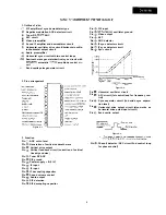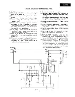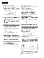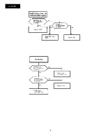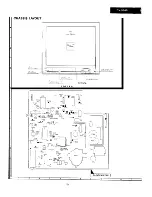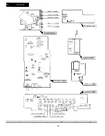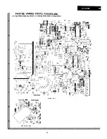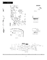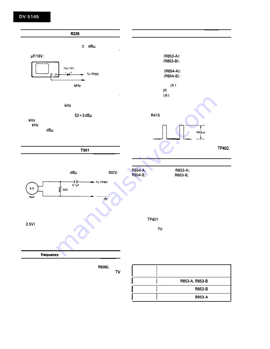
RF AGC cut-in adjustment:
1. Receive 10 ch. signal.
2. Set the signal input level at 52 1
3. Connect CR oscillator to TP202 across a capacitor of
10
This capacitor is to cut off DC supply.
To TP201
l
Oscillation frequency: 1
sine wave
l
Output voltage
: 0.1 vp-p
(when connected to TP202)
4. Adjust R225 so that 1
signal disappears from TV
screen.
5. Set the signal input level at
and check that
1
signal appears on TV screen.
If 1
signal does not appear, set the input signal
level at 52
again and follow the procedure in
step 4 again.
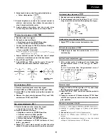
Sound detector coil adjustment:
1. Connect signal generator’s output to TP301.
l
Generator’s central frequency: 5.5 MHz
l
Modulation: No modulation
l
Generator output: 80
(terminated with
2. Connect DC voltmeter to TP302.
3. Adjust sound volume to minimum and measure the
voltage then available at TP302; this voltage (about
should be regarded as a reference voltage.
4. Adjust sound volume to maximum and turn the core
of T301 (sound detector coil) until DC voltmeter reads
the reference voltage obtained in step 3 above.
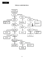
Horizontal
adjustment: R605
1. Receive monoscope pattern signal.
2. Short TP601 and TP602 (at both ends of
3. Adjust R605 to obtain good horizontal sync on
screen.
4. Remove the short-circuit between TP601 and TP602.
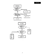
Sub-brightness adjustment: R415
1. Short TP401 and TP402.
2. Set each control as follows:
l
Screen control: at MIN position
l
G-bias control
at MIN position
l
B-bias control
at MIN position
l
R-bias control (R869): at MIN position
l
G-drive control
at CENTER position
l
B-drive control
at CENTER position
l
Contrast control (R 1110) : at M IN position
l
Brightness control
110): at CENTER position
l
Picture control 1110) : at CENTER position
l
Colour control
110) : at MIN position.
3. Receive monoscope pattern signal.
4. Connect oscilloscope to TP850 (with L2 connected to
ground)
5. Adjust
(sub-brightness control) so that the
output waveform on oscilloscope is at 15 Vp-p.
6. Remove the short-circuit between TP401 and
Background adjustment:
G-drive control,
G-bias control
B-drive control,
B-bias control
Screen control, R869; R-bias control
1. Receive monoscope pattern signal.
2. Set each control as follows:
l
Brightness control: at CENTER position
l
Contrast control: at MIN position
l
Screen control: at MIN position
l
G-, B-drive controls: at CENTER position
l
R-, G-, B-bias controls: at MIN position
3. Short
and TP402.
4. Turn screen control until horizontal raster slightly
appears on
screen.
5. One of the colours (R, G and B) appears first as
screen control is turned. So touching off the bias
control belonging to the first colour, adjust the other
controls as follows to make white the horizontal
raster.
First
colour
Bias controls to be next turned.
Red
Green
R869,
Blue
R869,
6. Turn screen control until the raster disappears and
stop it.
7. Remove the short-circuit between TP401 and TP402.
8. Set contrast control at MAX position.
10
Summary of Contents for DV-5145
Page 32: ...S H A R P T5157 S MW KY ...


