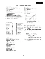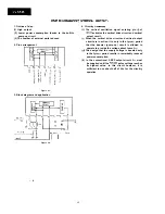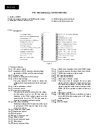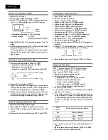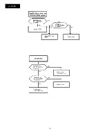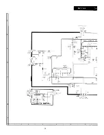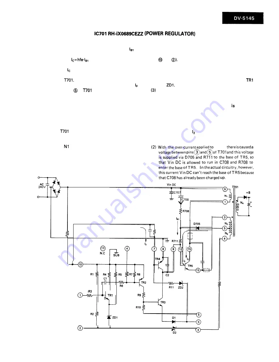
1. Oscillation principle
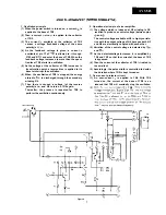
(1) When the power switch is turned on, a current
is
applied to the base of TR5.
(2) Then, a current
is applied to the collector
of TR5.
(3) The current available at the collector of TR5
causes a voltage (feedback voltage of the same
polarity) at
(4) As the feedback voltage is given, a current
available at pin
of
is allowed to
run
through
0705 and R711 and enter the base of TR5. When the
feedback voltage increases to more than the speci-
fied level, TR5 starts its oscillation.
(5) As the voltage at the collector of TR5 increases to
its saturation point, a reverse bias is applied to its
base to interrupt the oscillation.
(6) When th e oscillation of TR5 is stopped, the energy
stored in
is discharged through the secondary
winding N4.
(7) Then there is caused a voltage (of the reverse
polarity) at
and N2 to turn on TR5 again.
Thereafter, the process is repeated for TR5 to
perform the oscillation continuously.
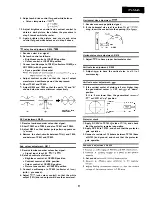
2. Operational principle of error amplifier
(1) The voltage which is induced at N3 winding is DC
rectified to produce a control voltage (between pins
and
The control voltage available at N3 is highly correla-
tive with the output voltage of N4 because both N3
and N4 are electrically coupled with each other.
(2) Variation of the control voltage is detected by
and
As the detec e voltage increases, it is amplified by
t d
TR2 and TR3 so that the current at the base of TR5
is bypassed.
(4) Then the current at the collector of TR5 limited to
the smallest.
(5) Accordingly, the pulse width is controlled to decide
the duration where TR5 is kept turned on.
3. Over-current protector circuit
(1) An over-current is applied to TR4. With TR4
turned on, the current at the base of TR5 is so
reduced that TR5 will eventually stop the oscillation.
TR5,
Figure 4.
7
Summary of Contents for DV-5145
Page 32: ...S H A R P T5157 S MW KY ...


