45
DV-L70S
DV-L70BL
DV-L70W
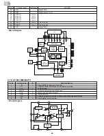
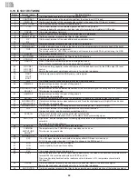
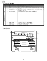
Pin No.
I/O
Terminal name
Operation function
Remarks
31
I
ST/MT
Input for destination setting
L: Japan
32
–
GND
GND
33
–
NC
Not used. (Pull-up)
34
O
MONO
Not used.
35
I
AFT
AFT voltage inputFrom LCD decoder IC
From TV tuner
36
O
PDET
Battery monitor AD input
37
I
AGC
AGC voltage input
From TV tuner
38
I
VOL
Not used.
39
I
POW IN
Power button input
40
I
IREM
Remote control input
From remote control light receiving unit
41
–
NC
42
O
MODW
Panel selection output (1)
To LCD control IC
43
44
MODN
Panel selection output (2)
45
O
VSW
Not used.
46
O
MIRST
DVD microcomputer reset output
To DVD system computer interface IC
47
O
DVD P
DVD circuit power control
To DVD power switch circuit
48
I
LCD SW
Liquid crystal panel open/close interrupt
From liquid crystal open/close detection switch
49
O
LCD H
Backlight ON/OFF control
From E
2
PROMTo liquid crystal inverter unit
50
–
NC
51
–
NC
52
O
LED1
LED control (green)
To LED lighting circuit
53
O
AV-S
TD/DVD video/audio selection output
To video SW IC/audio SW IC
54
O
LED2
LED control (red)
To LED lighting circuit
55
O
AV-P
TD/DVD video/audio selection output
To video SW IC/audio SW IC
56
O
DEF
Defeat output
57
O
EPCS
E
2
PROM chip select
To E
2
PROM
58
O
DACS
DAC chip select
To adjustment DAC IC
59
O
FLOF
PAL/NTSC switching terminal
60
O
IN H
External input control
To video SW IC/audio SW IC
61
I
PSW
Not used.
62
O
SMUTE
Audio mute output
To audio output circuit
63
64
–
NC
65
O
PMUTE
Video mute output
To LCD decoder circuit
66
I
ACL
ACL input
From 2VREG/reset generation IC
67
–
CLI
System clock input
Oscillator
68
–
CLO
System clock output
Oscillator
69
T1
Test input1
GND
70
T2
Test input2
GND
71
–
GND
Reference potential
GND
72
–
GND
Reference potential
GND
73
–
VDD
Power supply
4.5~5.5V
74
–
OSCI
Sign clock input
To OSD oscillation coil
75
–
OSCO
Sign clock output
To OSD oscillation coil
76
B
Blue sign output
To LCD decoder IC
77
G
Green sign output
To LCD decoder IC
78
R
Red sign output
To LCD decoder IC
79
FMCS
Not used.
80
–
NC.
Summary of Contents for DV-L70BL
Page 2: ...DV L70S DV L70BL DV L70W 2 1 IMPORTANT SAFEGUARDS AND PRECAUTIONS ...
Page 6: ...DV L70S DV L70BL DV L70W 6 For details on the use of each control 4 PART NAMES ...
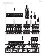
Page 53: ...53 DV L70S DV L70BL DV L70W 11 WIRING DIAGRAM ...
Page 82: ...Ref No Part No Description Code Ref No Part No Description Code 95 DV L70S DV L70BL DV L70W ...


