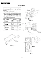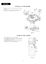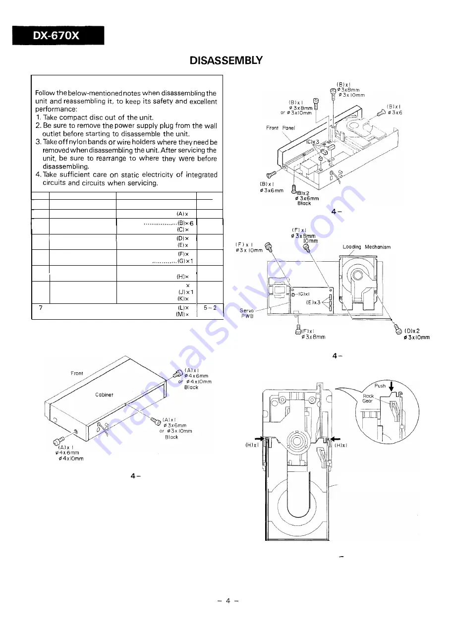
Caution on Disassembly
STEP
REMOVAL
PROCEDURE
FIGURE
1
Cabinet
1. Screw . . . . . . . . .
3
4 - l
2
Front Panel
1. Screw
4 - 2
2. Socket ................
3
3
Loading Mechanism
1. Screw .................
2
4 - 3
2. Socket . . . . . . . . .
3
4
Servo PWB
1. Screw . . . . . . . . . .
3
4 - 3
2 . S o c k e t
5
Disc Holder
1. Push the Rack Gear
4 - 4
2. Hook.. .................
2
6
CD Mechanism
1. Screw.. ................. (I) 2
5 - l
2. Shift Lever.. ...... . ...
3. Cushion.. .............
2
Display PWB
1. Screw.. ................
2
2. Hook.. ................
4
or
Block
Figure
1
o r
Figure
2
or
mm
0 3x
Block
Figure
3
Disc Holder
Figure 4 4


