Not used
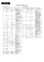
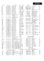
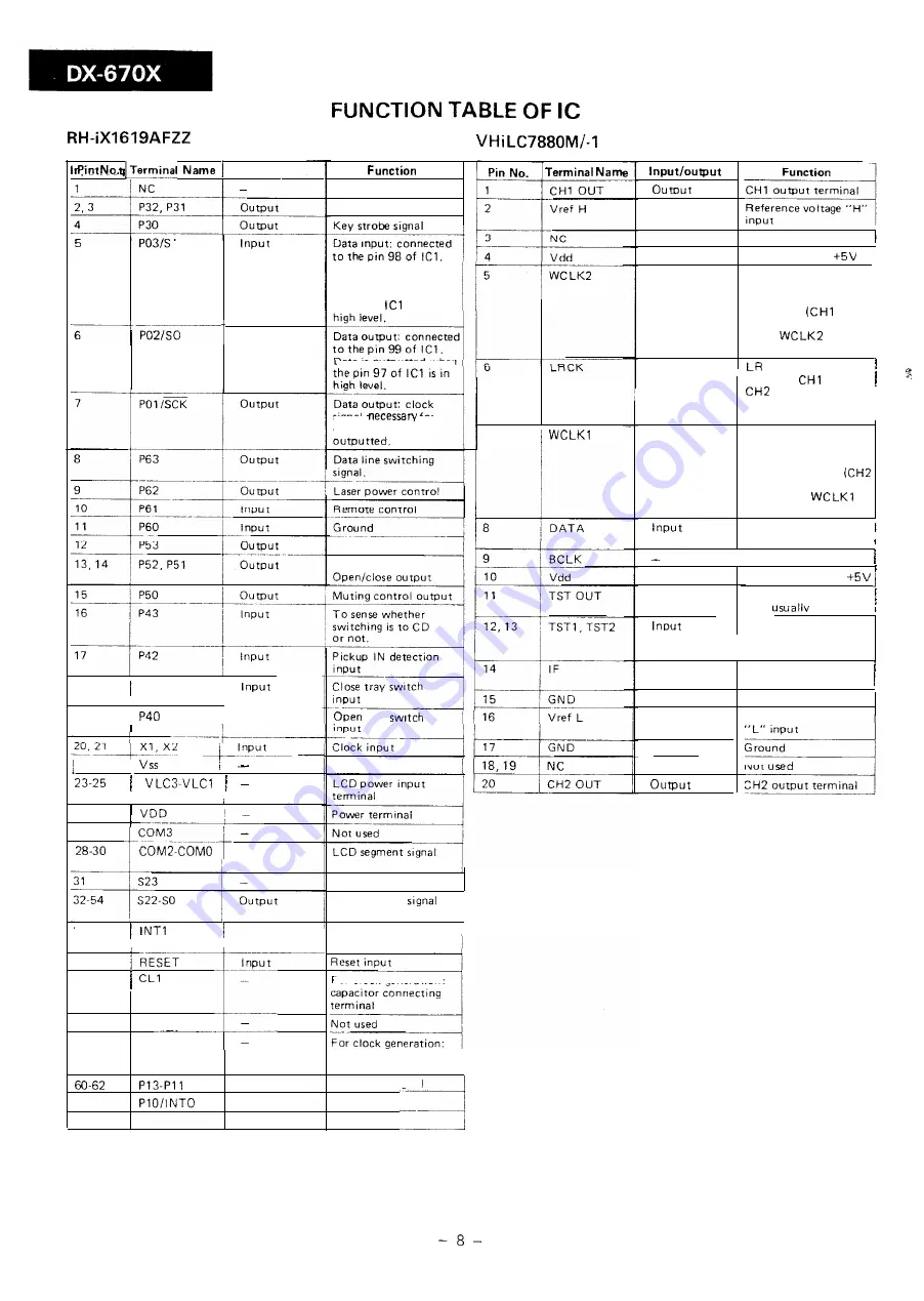
Key strobe signal
Data is inputted
according to SCK
clock input when the
pin 96 of
is in
Data is outputted when
signal
for
Input
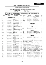
Not used
I
Power terminal
Input
Word clock 2 input
terminal: internal
signal to latch digital
audio data
data)
is generated by using
fall of
when
IF is in low level.
output
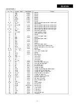
Input
clock 2 input
terminal:
and
of input digital
audio data are
indicated.
data transfer is
7
input
Word clock 1 input
terminal: internal
signal to latch the
digital audio data
data) is generated by
using fall of
when IF is in low level.
Digital audio data
input terminal
Remote control
Tray motor.
tray
Ground
output
Not used
Bit clock terminal
Power terminal,
Output terminal for
test:
open
output
Input terminal for
test: usually used for
grounding
i n t e r f a c e s w i t c h i n g
terminal
18
P41
Ground
Reference voltage
Not
19
Input
22
-
-
Input
26
I
27
output
55
Input
LCD segment
output terminal
Data transfer
I
request input
For clock generation:
capacitor connecting
terminal
56
57
58
VDD
59
CL2
63
64
Input
Input
P33 output
Key strobe signal
Ground
Not used


