background image

ER-A520/A530

– 3 –

CHAPTER 3. REMOTE DRAWER: 

ER-03DW, ER-04DW

1. OUTLINE

The ER-A520/530 allows connection of max, two remote drawers.

2. INSTALLATION PROCEDURE

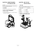
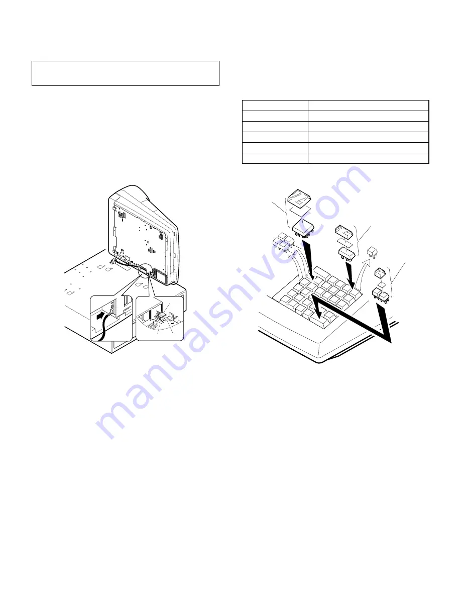
1) Remove the top cabinet.

2) Connect the remote drawer cable 

1

 to the drawer connector on

the main PWB. (Location: CN7)

CHAPTER 4. KEY TOP KIT

(ER-A520 ONLY)

1. OUTLINE

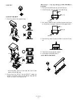
The ER-A520 employs the following key top (option) to allow additional

installation of the key top and change in the key layout.

2. INSTALLATION PROCEDURE

CAUTION:
The drawer unit should be securely fitted to the supporting platform
to avoid instability when the drawer is open.

CN6

CN7

1

MODEL NAME

DESCRIPTION

ER-11KT7

u

 1 Key top

ER-12KT7

u

 2 Key top

ER-22KT7

u

 2 Key top

ER-11DK7G

u

 1 Dummy key

ER-51DK7G

u

 1 Dummy key

ER-22KT7

ER-12KT7

ER-11KT7

Summary of Contents for ER-A520

Page 1: ...cument has been published to be used for after sales service only The contents are subject to change without notice ERA520UIME ELECTRONIC CASH REGISTER ER A520 MODEL ER A530 U A version ER A520 ER A530 CHAPTER 1 GENERAL 1 CHAPTER 2 DISASSEMBLY 2 CHAPTER 3 REMOTE DRAWER ER 03DW ER 04DW 3 CHAPTER 4 KEY TOP KIT ER A520 ONLY 3 CHAPTER 5 POLE DISPLAY UNIT UP P16DP 5 CHAPTER 6 EXPANSION RAM BOARD UP S02...

Page 2: ...Y FROM FIRE WHEN DISPOSING THE BATTERY FOLLOW THE LOCAL RULES AND REGULATIONS BATTERY DISPOSAL THIS PRODUCT CONTAINS LITHIUM BATTERY THIS BATTERY MUST BE DISPOSED OF PROPERLY REMOVE THE BATTERY FROM THE PRODUCT AND CONTACT FEDERAL OR STATE ENVIRONMENTAL AGENCIES FOR INFORMATION ON RECYCLING AND DISPOSAL OPTIONS TRAITEMENT DES ACCUMULATEUR USAGÉS CE PRODUIT CONTIENT UN ACCUMULATEUR À LITHIUM CET AC...

Page 3: ...ec essary measure against static electricity During operations disconnect the AC cord from the outlet After completion of operations connect the connectors After completion of operations be sure to perform the master reset OPTIONS NO CLASSIFICATION COMPONENT NAME MODEL NAME REMARK 1 Drawer Remote drawer ER 03DW ER 04DW 2 Key kit 1 x 1 key top kit 30 ER 11KT7 ER A520 only 1 x 2 key top kit 30 ER 12...

Page 4: ...op cabinet unit the grounding wire and connector cables from the top Cabinet are re moved 5 Remove the following cable 5 between the top cabinet and the main PWB 2 REMOVING THE PRINTER UNIT 1 Remove the top 1cabinet 2 Remove the two screws 1 fixed on the printer unit 3 Remove the screw 2 fixed on the earth wire 3 4 Remove the printer cable 4 from the MAIN PWB CN5 3 REMOVING THE CABINET 1 Remove th...

Page 5: ...P KIT ER A520 ONLY 1 OUTLINE The ER A520 employs the following key top option to allow additional installation of the key top and change in the key layout 2 INSTALLATION PROCEDURE CAUTION The drawer unit should be securely fitted to the supporting platform to avoid instability when the drawer is open CN6 CN7 1 MODEL NAME DESCRIPTION ER 11KT7 1 u 1 Key top ER 12KT7 1 u 2 Key top ER 22KT7 2 u 2 Key ...

Page 6: ... u 2 key top installing jig UKOG 6725BHZZ for installation 1 Remove the key label and the key cap from the key top 2 Attach the key top so that the guide arm is under the jig 3 With the jig inserted in the key top slowly press down the key top until the guide arm is brought into contact with the guide holder A 4 Remove the jig under the above condition 3 and press the key top 5 Check that the key ...

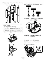
Page 7: ...1 Remove the five screws 1 2 Remove the Base angle 2 3 Remove the two screws 6 4 Remove the Base cabinet 4 from the pole cabinet 7 5 Turn the ratchet 9 connected to the pole cabinet 7 to the remov ing position and pull it out from the display unit 8 as shown in Fig A 6 Remove the two screws F 7 Remove the pole cabinet 7 from the Ratchet 9 No NAME USE Q ty G Pole cabinet Pole extension 2 H Screw M2...

Page 8: ...ER 6 EXPANSION RAM BOARD UP S02MB CHAPTER 7 DRAWER POSITION CHANGE 1 Remove the cabinet fixing screw 1 2 Slide the cabinet to the left and remove the cabinet 3 Insert the pawl of the cabinet into the hole A at the back 4 Slide the cabinet to the right 5 Tighten the cabinet fixing screw 1 No NAME USE Q ty I Screw M4 x 16 Securing the UP P16DP to the wooden table 4 J Screw M4 x 20 Securing the UP P1...

Page 9: ... November Printed in Japan t COPYRIGHT 2004 BY SHARP CORPORATION All rights reserved Printed in Japan No part of this publication may be reproduced stored in a retrieval system or transmitted In any form or by any means electronic mechanical photocopying recording or otherwise without prior written permission of the publisher ...

Reviews: